Loop-powered RADAR transmitters
Innovative loop-powered RADAR level transmitter ideal for challenging high-pressure applications. Features guided wave technology, HART communications, and user-friendly interface. Apply in hazardous areas and high-temperature environments worldwide.
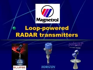

Loop-powered RADAR transmitters
E N D
Presentation Transcript
Eclipseis a two wire, loop powered, 24vDC level transmitter based on Guided Wave Radar and offered with a 2 line x 8 character display and/or HART communications.
How Does It Work? • Pulses of high frequency energy are sent down a probe (wave guide) and timing circuitry measures the reflection of the signal off the surface of the process • The higher the dielectric, the stronger the return signal
Wiring Compartment Electronic Nameplate Terminal Connection board Electronic Compartment Explosion-proof and Watertight feedthrough Display Keypad Digital Circuitry Universal High Frequency Connector TDR Circuitry
Advantages • Compact and lightweight • Loop-powered for ease of installation • Top-mounted with with quick connect and disconnect feature • Ergonomic and functional dual-chamber enclosures rotate 360º • HART and AMS capable • 13 probes (coaxial, twin-rod, single rod)
Advantages • Challenging applications that include shifting and changing media • High temperature & high pressure applications • Menu driven user interface with simple straightforward set-up and configuration • International hazardous location approvals • Proven performance with more than 12000 units installed worldwide
Where to apply • Challenging applications (saturated steam, 100% full vessels or chambers, extremes in temperature and pressure; dielectric media as low as 1.4; shifting gravity and dielectric media • Wide probe selection accomodates a broad range of media – from solvents to viscous Bunker C fuel oils and coating media such as latex paints
Where to apply • Hazardous area service in Power, Offshore/Onshore production, Refining, Chemicals and Petrochemicals • Tanks and vessels up to 20 feet high (705) and 50 feet high (708) • Interface measurement up to 12 feet (707)
Where to apply • Applications where traditional instruments have not fulfilled user expectations for reliability or performance (i.e. DP or RF transmitters, Torque Tube transmitters/controllers, Magnetostrictive devices)
Where to exercise caution • Vessel or media are at or near the maximum capabilities of Eclipse • Caustic or acidic media may present corrosion-related problems for the probe • Probe may encounter bridging due to dirty or highly viscous media • Excessive vortices or agitation that may damage the probe • Boiling and/or flashing may occur
Where NOT to apply • Eclipse maximum operating temperatures, pressures or specifications are exceeded • Media with dielectric < 1.4 • Tank heights greater than 50 feet • Headroom does not permit safe installation of a rigid probe • Interface applications where upper and lower dielectric media are out of range • Top medium is higher dielectric than lower medium (707 only)
Where to usePULSAR instead • Medium’s viscosity exceeds selected probe’s capabilities • Diminished headroom only allows for use of radar transmitter with small antenna • Long probes are difficult or unsafe to install • End-user prefers non-contact devices • Corrosion or viscosity conditions favor specification of non-contact device
Horizon Model 703 Horizon Model 703 • Cost effective blind transmitter in a single-compartment housing • Pushbutton Calibration with a 3-pushbutton, 3 LED user interface • Level movement or “Level-simulation” required for calibration
Horizon Model 704 Horizon Model 704 • Intermediate transmitter in a single-compartment housing • Optional LCD and HART output • No level movement required for configuration
Advantages • Stripped-down Eclipse versions for simple applications • 703 simplest version, very economical • 704 same display as Eclipse • Compact, lightweight and affordable • Loop-powered for ease of installation • Broad range of industry segments and applications
Advantages • Choice of plastic or aluminum single compartment enclosure • Coaxial, twin-rod and single rod probes up to 16 feet • General purpose areas in clean industry applications where XP is not needed (Valox housing versions) • Worldwide safety approvals
Where to apply • 703: OEM, water-wastewater and general non-hazardous locations • 704: Hygiene-intensive industries where 3-A authorized probe, Tri-Clamp fiting and a plastic housing make easy CIP while eliminating an oxydation threat • Either: Tanks, open channels, pits, sumps or wet wells up to 16 feet tall • Applications within unit’s specifications
Where to exercise caution • Vessel or media are at or near the maximum capabilities of Horizon • Caustic or acidic media may present corrosion-related problems for the probe • Probe may encounter bridging due to dirty or highly viscous media • Excessive vortices or agitation that may damage the probe • Boiling and/or flashing may occur
Where NOT to apply • Maximum operating temperatures, pressures or specifications are exceeded • Media with dielectric < 1.7 • Tank heights greater than 16 feet • Headroom does not permit safe installation of a rigid probe
Where to usePULSAR instead • Medium’s viscosity exceeds selected probe’s capabilities • Diminished headroom only allows for use of radar transmitter with small antenna • Long probes are difficult or unsafe to install • End-user prefers non-contact devices • Corrosion or viscosity conditions favor specification of non-contact device
Antenna Offering 400F (204C) 200F (93C) 400F (204C) TFE Polypropylene 4” 6” Min. Dielectric 2.0 1.7 675psig (46.5bar) 750psig (51.7bar) 675psig (46.5bar)
Advantages • Compact, lightweight and affordable • Loop-powered for ease of installation • Non-contact technology, top-mounted with quick connect/disconnect • Unaffected by fumes and vapors above the process level • Tolerates turbulence and light to medium density foam
Advantages • Quick-Start procedures simplify set-up and start-up • Dual compartments for convenient wiring and display • Changing dielectrics or conductivity do not affect measurement accuracy • Advanced signal processing extracts true level from false reflections • Avail. 4” & 6” metal horn and dielectric rod antennas (polypropylene and Teflon)
Where to apply • Where measuring requirements exceed capabilities of Eclipse GWR • Where Pulsar is more cost effective due to the probe length of GWR • Vessels where there is insufficient headroom for a probe instrument • When user prefers non-contact devices • Highly viscous, coating media which could cause bridging of GWR probes
Where to exercise cautions • Vessel contents may reach 100% full point, or within 2” of the antenna • Very low dielectric media combined with very long measurement ranges • Vessels containing low dielectric media which normally operate at very low level • Tanks with internal obstacles, or where severe turbulence or foam exists • Vessels operating at or near the maximum recommended operating conditions
Where NOT to apply • Where the maximum operating specifications are exceeded • Dielectrics below 1.7 for horn antennas or 2.0 for dielectric rods • Acids, corrosives or caustics incompatible with antennas or process seal/connections • Extreme turbulence, excessive foam, vortices or rollover process conditions • Excessive product build-up on antenna • Standpipes and stillwells
Where to useGWR instead • Excessive foam is present • Dielectrics below 1.7 • Low dielectric media (1.7<e<2.0) combined with very low product levels • Extremely short measuring ranges • Toperating > 400ºF • Poperating > 750 psig @ +70ºF
Where to useGWR instead • Saturated steam applications (deaerators or steam drums) • Overfill conditions(applications require 100% of total capacity) • Sanitary applications requiring 3-A Authorization
The Most Potent Combination in the Level Measurement Industry!