Aligning ND280 Magnet Modules: Ensuring Accurate Measurements and Clearances
This document addresses the critical alignment and mounting issues of ND280 magnet modules necessary for accurate measurements. We propose a common reference frame for alignment, focusing on the clearance between counters and modules. Key proposals include aligning all modules on a consistent plane (B*), installing counters in specific sections to mitigate exposure to the elements, and ensuring horizontal rails for proper alignment across various sectors. These steps are vital to avoid discrepancies in measurements that could impact the performance of the scintillation counters.

Aligning ND280 Magnet Modules: Ensuring Accurate Measurements and Clearances
E N D
Presentation Transcript
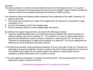
Questions • The obvious problem is to define common reference frame for all the measurements. In our opinion there are 3 questions concerning alignement and mounting of ND280 magnet. Without knowing the answers it would not be possible to estimate the thickness of SMRD counters. • In an attempt to define this reference frame necessary for the estimation of the width (“clearance”) of gaps we assumed: • the counters are mounted from 2 sides of the magnet joke: the clearance is calculated for a gap consisting of 4 C’s. • for all C’s the planes A and B* form straight angle. • the front and back sides of C’s form straight angle with plane A. • According to the magnet measurements, we propose the following procedure: • There are substantial differences in the measured distances between B*B reference planes for different modules (up to 64 mm between C1 – C2 modules). In a case of magnet alignement on plane B these differences would be critical for clearance in vertical sectors (Vc, Vd, Ve and Vf). Therefore we would propose to aligne all the modules C on planes B*. For such an alignement the differences in the B*-B distances would be irrelevant. • 2. The differences between measured distances between A*A are of the order of few mm. Therefore we would like to propose to install the counters in sections Hg and Hh before putting the C’s into the pit. If the SiPM’s would suffer from the outside weather we propose to install outside only the scintilators, and the SiPM’s when the C wuold be in the pit. • 3. The rails supporting all modules C should be horizontal and flat – this would guarantee the correct alignement of gaps in sectors Ha and Hb. • Critical would the alignement of C’s on plane A and plane B*.