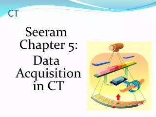
Seeram Chapter 5: Data Acquisition in CT
990 likes | 2.97k Vues
CT. Seeram Chapter 5: Data Acquisition in CT. Data Collection Basics. Patient. X-ray source & detector must be in & stay in alignment Beam moves (scans) around patient many transmission measurements. X-Ray beams. Data Collection Basics. Pre-patient beam

Seeram Chapter 5: Data Acquisition in CT
E N D
Presentation Transcript
CT Seeram Chapter 5: Data Acquisition in CT
Data Collection Basics Patient • X-ray source & detector must be in & stay in alignment • Beam moves (scans) around patient • many transmission measurements X-Ray beams
Data Collection Basics • Pre-patient beam • collimated to pass only through slice of interest • shaped by special bow tie filter for uniformity Patient Filter
Data Collection Basics (cont) • Beam attenuated by patient • Transmitted photons detected by scanner • Detected photon intensity converted to electrical signal (analog) • Electrical signal converted to digital value • A to D converter • Digital value sent to reconstruction computer
CT “Ray” • That part of beam falling onto a single detector Ray
Each CT Ray • attenuated by patient • projected onto one detector • detector produces electrical signal • produces single data sample
CT View • # of simultaneously collected rays
Scan Requires Many Data Samples • # Data Samples = [# data samples per view] X [# views] • # Data Samples = [# detectors] X [# data samples per detector]
Acquisition Geometries • Pencil Beam • Fan Beam • Spiral • Multislice
Pencil Beam Geometry Tube Detector • Tube-detector assembly translates left to right • Entire assembly rotates 1o 1st Generation CT 1o Pencil Beam
Fan Beam Geometry Tube Detectors 3nd Generation Fan Beams 2nd Generation 4th Generation
Comparing Long vs. Short Geometry Long Geometry • Smaller fan angle • Longer source-detector distance • Lower beam intensity • Lower patient dose • More image noise • Less image blur • Requires larger gantry Scan FOV Scan FOV Short Long
Spiral Geometry Interconnect Wiring Tube Slip Rings Detector • X-ray tube rotates continuously around patient • Patient continuously transported through gantry • No physical wiring between gantry & x-ray tube • Requires “Slip Ring” technology
Slip Rings • Electrical connections made by stationary brushes pressing against rotating circular conductor • Similar to electric motor / generator design
X-Ray Generator Configurations with Slip Ring Technology • Problem: • Supply high voltage to a continually rotating x-ray tube? • Options • #1 • Stationary Generator & Transformer • #2 • Stationary Generator • Transformer & x-ray tube rotate in gantry • #3 • Transformer, generator & tube rotate in gantry
Option #1: Stationary High Voltage Transformer Primary Voltage Secondary Voltage Incoming AC Power X-Ray Generator High Voltage Transformer X-Ray Tube Stationary Rotating Slip Rings
Option #1: Stationary High Voltage Transformer Secondary Voltage Line Voltage Primary Voltage Tube Slip Rings Detector Generator • high voltage must pass through slip rings HV Transformer
Option #2: Rotating High Voltage Transformer Primary Voltage Secondary Voltage Incoming AC Power X-Ray Generator High Voltage Transformer X-Ray Tube Stationary Rotating Slip Rings
Option #2: Rotating High Voltage Transformer Line Voltage Primary Voltage HV Transformer Tube Slip Rings Detector Generator • low voltage must pass through slip rings
Rotating Generator Primary Voltage Secondary Voltage Incoming AC Power X-Ray Generator High Voltage Transformer X-Ray Tube Stationary Rotating Slip Rings
Rotating Generator Line Voltage Generator Tube Slip Rings HV Transformer • low line voltage must pass through slip rings
Spiral CT Advantages • Faster scan times • minimal interscan delays • no need to stop / reverse direction of rotation • Slip rings solve problem of cabling to rotating equipment • Continuous acquisition protocols possible
X-Ray System Components • X-Ray Generator • X-Ray Tube • Beam Filter • Collimators
X-Ray Generator • 3 phase originally used • Most vendors now use high frequency generators • relatively small • small enough to rotate with x-ray tube • can fit inside gantry
X-Ray Tube • Must provide sufficient intensity of transmitted radiation to detectors • Radiation incident on detector depends upon • beam intensity from tube • patient attenuation • beam’s energy spectrum • patient • thickness • atomic # • density
Maximizing X-Ray Tube Heat Capacity • rotating anode • high rotational speed • small target angle • large anode diameter • focal spot size appropriate to geometry • distances • detector size
Special Considerations for Slip Ring Scanners • continuous scanning means • Heat added to tube faster • No cooling between slices • Need • more heat capacity • faster cooling
Why not use a Radioactive Source instead of an X-Ray Tube? • High intensity required • X-ray tubes produce higher intensities than sources • Single energy spectrum desired • Produced by radioactive source • X-ray tubes produce spectrum of energies • Coping with x-ray tube energy spectrum • heavy beam filtering (see next slide) • reconstruction algorithm corrects for beam hardening
CT Beam Filtration • Hardens beam • preferentially removes low-energy radiation • Removes greater fraction of low-energy photons than high energy photons • reduces patient exposure • Attempts to produce uniform intensity & beam hardening across beam cross section Patient Filter
CT Beam Collimation • Pre-collimators • between tube & patient Tube • Post-collimators • between patient & detector Detector
Pre-Collimation Tube Detector • Constrains size of beam • Reduces production of scatter • May have several stages or sets of jaws Pre-collimator
Post-Collimation Tube Detector • Reduces scatter radiation reaching detector • Helped define slice (beam) thickness for some scanners Post-collimator
CT Detector Technology:Desirable Characteristics • High efficiency • Quick response time • High dynamic range • Stability
CT Detector Efficiency • Ability to absorb & convert x-ray photons to electrical signals
Efficiency Components • Capture efficiency • fraction of beam incident on active detector • Absorption efficiency • fraction of photons incident on the detector which are absorbed • Conversion efficiency • fraction of absorbed energy which produce signal
Overall Detector Efficiency Overall detector efficiency = capture efficiencyXabsorption efficiencyXconversion efficiency
Capture Efficiency • Fraction of beam incident on active detector
Absorption Efficiency • Fraction of photons incident on the detector which are absorbed • Depends upon detector’s • atomic # • density • size • thickness • Depends on beam spectrum capture efficiencyXabsorption efficiencyXconversion efficiency
Conversion Efficiency • Ability to convert x-ray energy to light GE “Gemstone Detector” made of garnet
Conversion Efficiency • Ability to convert x-ray energy to light • Siemens UltraFastCeramic (UFC) CT Detector • Proprietary • Fast afterglow decay UFC Plate UFC Material
Response Time • Minimum time after detection of 1st event until detector can detect 2nd event • If time between events < response time, 2nd event may not be detected • Shorter response time better
Stability • Consistency of detector signal over time • Short term • Long term • The less stable, the more frequently calibration required
Dynamic Range • Ratio of largest to smallest signal which can be faithfully detected • Ability to faithfully detect large range of intensities • Typical dynamic range: 1,000,000:1 • much better than film
Detector Types: Gas Ionization Electrical Signal X-Rays • X-rays converted directly to electrical signal Filled with Air Ionization Chamber + - + -
CT Ionization Detectors • Many detectors (chambers) used • adjacent walls shared between chambers • Techniques to increase efficiency • Increase chamber thickness • x-rays encounter longer path length • Pressurize air (xenon) • more gas molecules encountered per unit path length thickness X-Rays
Older Style Scintillation Detectors • X-rays fall on crystal material • Crystal glows • Light flash directed toward photomultiplier (PM) tube • Light directed through light pipe or conduit • PM tube converts light to electrical signal • signal proportional to light intensity PM Electrical Signal
Detector Types: Scintillation Light X-Rays • X-ray energy converted to light • Light converted to electrical signal Photomultiplier Tube Electrical Signal Scintillation Crystal
Photomultiplier Tubes • Light incident on Photocathode of PM tube • Photocathode releases electrons + - Light X-Rays Scintillation Crystal Photocathode PM Tube Dynodes