Download
1 / 19
190 likes | 463 Vues
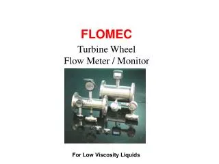
FLOMEC. Turbine Wheel Flow Meter / Monitor. For Low Viscosity Liquids. Flomec. Description. Turbine Wheel Flow Meter / Monitor The TP turbine wheel flow meter is highly accurate, reliable & used to measure the flow of clean low viscosity fluids & utilizes a proven flow meter technology.

E N D
FLOMEC Turbine Wheel Flow Meter / Monitor For Low Viscosity Liquids
Flomec Description • Turbine Wheel Flow Meter / Monitor • The TP turbine wheel flow meter is highly accurate, reliable & used to measure the flow of clean low viscosity fluids & utilizes a proven flow meter technology. • The turbines design is based on a freely suspended turbine rotor which is rotated by the flow of fluid through the meter body
Fig.1 Bearing supports Rotor shaft & rotor Circlip Flomec Operation • Turbine Wheel Flow Meter / Monitor Principal of operation The TP Turbine Wheel flow meter consists of a helically shaped turbine rotor supported in two tungsten carbide bearings, the rotor being solid ferritic stainless steel of a grade compatible with the metered liquid, is all contained within a housing of non-magnetic stainless steel. (fig.1).
Flomec Operation Principal of Operation Pick - Off coil Fig 2 A pick off coil having a permanent magnet core is mounted in the housing adjacent to the rotor blade tips such that a magnetic circuit is set up via the rotor blades (fig.2). Rotation of the rotor varies the reluctance of this Pick off coil magnetic circuit and the flux changes induce a small voltage in the coil, the frequency of which is directly proportional to the rotor speed and therefore proportional to the volumetric flow rate. Rotor Blades
Flomec Turbine Wheel Features • Stainless steel body • Tungsten carbide shaft & bearings • Frequency output • Pressures to 250 bar • Pipe sizes 1/2” to 6” (15-150mm) • +/- 0.5% linearity ( 10:1 turndown ) • Minimal pressure loss • Simple to install • Temperature 120 deg C standard • European CE compliant. • Flanged or Screwed
gal RUN ACCUM. TOTALSTOP BAT LOW HIGH ACCUM ^ TOTAL RESET RATE PROGRAM > ENTER TOTAL Flomec Turbine Wheel Options • High temperature to 2400 C • +/- 0.15% linearity. • 2 pick off coils – 90 deg. offset • Integral or remote high speed preset batch controller • Integral or remote self powered flow • rate totaliser with scaled pulse, 4-20 mA • and flow alarm outputs. • Optional Bi-directional discriminator • output.
Flomec Turbine Wheel Outputs • Frequency output - 2 wire reluctance pick off coil. ( 40mV P/P at minimum flow rate ) • Suitable for direct input to a wide range of ancillary instruments. • Polarity insensitive - 20 meters transmission distance standard. • IP66 / 67 protection class.
screen twisted pair Receiving instrument Pick-off coil screen use twisted pair coil output with MS connector ( A & B ) screen earthed at junction box & connect to -0V at receiving instrument coil output with junction box Flomec Turbine Wheel Outputs Electrical Connections Because of the low strength of the standard coil mV output it is important to protect the transmitted signal from any form of electrical interference such as AC line frequencies. A twin core ( twisted pair ) screened multi-strand signal cable should be used for connection to the pick-off coil, recommended cable size being 16/0.2 x 0.5mm² ( 16/0.0078 ). The screen needs to be connected at -0V at receiving instrument
gal RUN ACCUM. TOTALSTOP BAT LOW HIGH ACCUM ^ TOTAL RESET RATE PROGRAM screen twisted pair Pick-off coil screen use twisted pair > coil output with MS connector ( A & B ) ENTER TOTAL Flomec Kobold Turbine Wheel Outputs 20 meters max. Electrical Connections Cable runs for non amplified outputs should be limited to 20 metres (65 feet) maximum and should be kept well away from high energy power supplies and electricals such as motor speed controllers, transformers and solenoids. Preferably run the cable in a separate conduit to any other wiring. Longer cable runs would require an amplifier at the flow meter
Flomec Turbine Wheel Outputs • Preamplifier coil ( optional ) • An amplified output can be provided by fitting a pre-amplified coil. The pre-amplifier coil amplifies the low level signal from the integral magnetic pick-off providing a current pulsed output suitable for transmission over long distances or through noisy electrical environments. The output is a current pulse in the order .. Shield + 9~24Vdc Receiving instrument ( - ) Amplified current pulse output with MS connector. of 4mA (off) and 20mA (on)
min. 5 pipe diameters min. 10 pipe diameters Fig.2 Flomec Installation Meter orientation The meter may be installed in horizontal or vertical pipes, with vertical pipes it is preferred to have the flow passing upward so that any entrained air bubbles will pass quickly. Ensure that the arrow on the meter body is in line with the direction of flow. Flow conditioning All turbine flow meters should be installed with a minimum of ten diameters of straight pipe up-stream and five diameters down-stream (fig. 2), except where the flow meter is installed directly after a valve or centrifugal pump when the minimum straight up-stream length should be increased to 20 diameters.
Flomec Installation Flow Conditioning Bends & elbows up-stream of the flow meter should have a minimum inside radius of twice the diameter of the pipe. Ensure flange gaskets are bore size matched with meter. 22~30º Reducers where necessary should be of the concentric type with an included angle of 22~30 degrees (fig. 3) Fig 3 Inlet pipe bore should be matched as closely as possible to that of the meter, but where it is not possible to select the exact inside diameter, a smaller inlet diameter should be used in order to avoid a sharp step at the meter inlet which would cause liquid swirl effecting metering accuracy.
Rotor leading edge (angled) Rotor trailing edge (squared) FLOW DIRECTION viscosity [cSt ] ) x normal min. flow rate ( 0.7 Bearing supports Flomec Fluid Flow in Pipes Viscosity effects The effects of increasing viscosity reduce the linear flow range, the lower end flow rate is to be raised as the viscosity increases with a maximum viscosity of 10cSt. To calculate the low end accurate flow rate limit use: 0.7 x the square root of the metered liquid viscosity in cSt x normal minimum flow rate. Eg. If normal flow range is 10~100 l/min then for viscosity of 5 cSt minimum accurate flow rate would be 15.65 l/min.
Flomec Applications Applications Typical industry applications include: (Liquids with viscosity below 10 cSt.) Chemicals & allied Products. Pharmaceuticals. Fuel consumption Fuel additives Deionised water Hydraulics Coolants Batching & blending Liquid Fertilizer
Flomec Specifications Model Prefix TP Series Suit Pipe Sizes 15- 150 mm (1/2" - 6") Process connection Screwed or flanged Body Material 316 stainless steel body & rotor shaft Rotor Material 316 stainless steel Viscosity Limit 10 mm2/s. ( 10cSt ) Flow Range 0.11 – 550 M3/hr. Linearity @ 1cP Linearity typically +0.5%, of Reading +1%, Repeatability +0.2%, under steady flow conditions Maximum Pressure Threaded to 250 bar, flanged according to flange specification Pressure Drop Approx. 0.28 bar at maximum flow ( SG=1, Viscosity=1 mm2/s )
Flomec Specifications TP Series Model Prefix Outputs (standard) 2 Wire reluctance type pick-off coil (40mV P/P at minimum flow rate ) Polarity insensitive 20 metres maximum transmission distance Preamplifier 2 wire 4mA (off) and 20mA (on) current pulse (12…24Vdc ) 3000 metres maximum transmission distance Protection Class IP66 / 67 Recommended Filters Sizes up to 50mm ( 300 microns or 60 mesh Sizes 80mm and above ( 500 microns or 100 mesh ) Temperature Minus 50 to plus 120 deg .C optional 240 deg. C
Flomec Ordering Information Turbine Wheel flow meter TP Series TP-12 Stainless Steel / Carbon Steel TP-13 Stainless Steel / Stainless Steel Body Material 316 stainless steel. TP-13 Screwed Range Connection • 05 = 0.11 – 1.1 m3/h • G4 = ½” male • 10 = 0.22 - 2.2 m3/h • = 0.40 - 4.0 m3/h • 20 = 0. 80 - 8.0 m3/h G5 = ¾” male • 25 = 1.60 - 16.0 m3/h • G6 = 1” male • 30 = 3.40 - 34.0 m3/h • G8 = 1 1/2” male • 35 = 6.80 – 68.0 m3/h • G9 = 2” male • XX = Special Option • XX = Special Option
Flomec Ordering Information Turbine Wheel flow meter TP Series TP-12 / 13 Flanged Range Connection • 05 = 0.11 – 1.1 m3/h • F4 = DN15, PN16 • 10 = 0.22 - 2.2 m3/h • = 0.40 - 4.0 m3/h • 20 = 0. 80 - 8.0 m3/h F5 = DN20, PN16 • 25 = 1.60 - 16.0 m3/h • F6 = DN25, PN16 • 30 = 3.40 - 34.0 m3/h • F8 = DN40, PN16 • 35 = 6.80 – 68.0 m3/h • F9 = DN50, PN16 • 40 = 13.5 – 135 m3/h • FB = DN80, PN16 • 45 = 27.0 – 270 m3/h • FC = DN100, PN16 • 50 = 55.0 – 550 m3/h • FB = DN150, PN16 • XX = Special Option • XX = Special Option
Ordering Information Flomec Insertion Paddle Wheel TP Series Order Example: DOT-13 15 N5 F1 B1 0 Pick-off Style / Type M1 = MS ( military style ) connector for 120 deg C max. M2 = MS ( military style ) connector for 240 deg C max. M4 = MS ( military style ) connector pre-amplified for 65 deg C max. F1 = Flying leads ( compact meter mount, see electronics ) for 120 deg C max. XX = Special Option F6 = NPN OC + 1.5V – integral electronic ZOD on stem kit Electronics -00 =Frequency output only FBT11= Electronic Totalizer FRT12 = Electronic Rate / Totalizer FRT20 = Electronic Rate / Totalizer FEB1 = Electronic Batch Controller XX = Special option ( specified in clear text ) Special options None = Without options Y = Special option (specified in clear text ) B = Linearity 0.15% ( instead of 0.5% ) 2 = 2 x Pick off coils