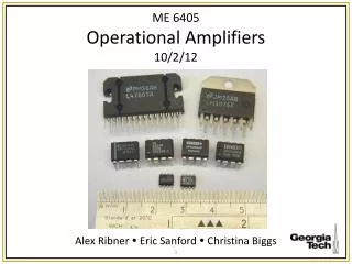
Operational Amplifiers ME 6405, Fall ‘04
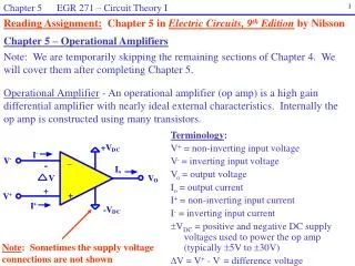
Operational Amplifiers ME 6405, Fall ‘04. Martin Gudem Nurudeen Olayiwola Henry Won. Operational Amplifiers. Goals: Introduction Characteristics Types Models VS. reality. Introduction. Most transducers provide analog signals: Too small Too noisy. Wrong information DC offset.

Operational Amplifiers ME 6405, Fall ‘04
E N D
Presentation Transcript
Operational AmplifiersME 6405, Fall ‘04 Martin Gudem Nurudeen Olayiwola Henry Won
Operational Amplifiers Goals: • Introduction • Characteristics • Types • Models VS. reality
Introduction Most transducers provide analog signals: • Too small • Too noisy • Wrong information • DC offset Measurement system
Amplifiers • Ideally: Increase amplitude without affecting other properties of the signal • Voltage gain: • Impedances:
Terminology Open loop Closed loop Stabilized signal
Ideal Model • Aid in circuit analysis • I+ = I- = 0 • V+ = V- • Zout = 0
Configuration • 741 General purpose amplifier Pin-out
The Ideal Op-Amp • Infinite Input Resistance • Zero input current • Zero Output Resistance • Infinite Gain • Common Mode Voltage Gain Zero • Zero Noise / Zero Output Allowed • Unlimited Bandwith • Temperature Independent
Ideal v. Real Op-Amps http://hyperphysics.phy-astr.gsu.edu/hbase/electronic/opampcon.html#c1
Op-Amps for Math • Inverting • Non-Inverting • Summing • Differencing • Integrating • Differentiating
Inverting “An Application Guide for Op-Amps”, National Semi-Conductor, Application Note 20, February 1969.
Non - Inverting “An Application Guide for Op-Amps”, National Semi-Conductor, Application Note 20, February 1969.
Summing Op-Amp “An Application Guide for Op-Amps”, National Semi-Conductor, Application Note 20, February 1969.
Differencing Op-Amp “An Application Guide for Op-Amps”, National Semi-Conductor, Application Note 20, February 1969.
Integrating Op-Amp “An Application Guide for Op-Amps”, National Semi-Conductor, Application Note 20, February 1969.
Differentiating Op-Amp “An Application Guide for Op-Amps”, National Semi-Conductor, Application Note 20, February 1969.
Use of an Op amp • Filters: 3 types • Low Pass Filter (LPF) • Used to filter higher freq. • High Pass Filter (HPF) • used to filter low freq. • Band Pass Filter (BPF) -a combination of LPF and HPF
Contd. • Dual input (dual source – and + with respect to ground), • Used in audio equip. control circuits, medical equipment, etc. • Single input
Order of filters • First order • Second order Our examples show second order Filters. - What was the order of the filter we used in lab?
LPF This filter is used to remove noise signals that are above the specified frequency. The frequency range is given by the equation below Where f=freq. R=R2 C=C1
HPF HPF is used to remove all freq. Below the specified freq. and it is Created by reversing the position of the capacitor and resistor In a LPF
BPF This is a combination of the LPF and HPF. It allows for freq. within the range for the LPF and HPF.
Instrumentation OP Amp This is used in Situations where output voltage needs to varied.
Analysis of instrumentation op amp • Vo = Vo1 – Vo2 • Vo1=V1+VR • Vo2 =V2 – VR • VR = (V1-V2)R/RA • Vo= V1-V2+2VR =(V1-V2)(1+2R/RA)
The use of filters • Communications • Removing noise from a power input • Radio communications • Infrared/ LED signals transm. • Etc
Conclusions • One major disadvantage • Distortion when dealing with really low freq. ranges
Conclusions contd. • Advantages • Useable in different industries • Signal and power amplification • Simple • Cheap and easy to build • Makes life easier • Math operations
References • www.electronics-tutorials.com • www.play-hookey.com • Alcitore, Histand Introduction to Mechatronics and Measurement Systems