Construction of Micropiles for Limited Headroom Site
330 likes | 350 Vues
This project showcases the construction process of micropiles in areas with limited headroom. It includes various steps such as drilling, installing reinforcements, injecting grout, and constructing pile caps. The site plan, equipment, and instruments used are also featured.

Construction of Micropiles for Limited Headroom Site
E N D
Presentation Transcript
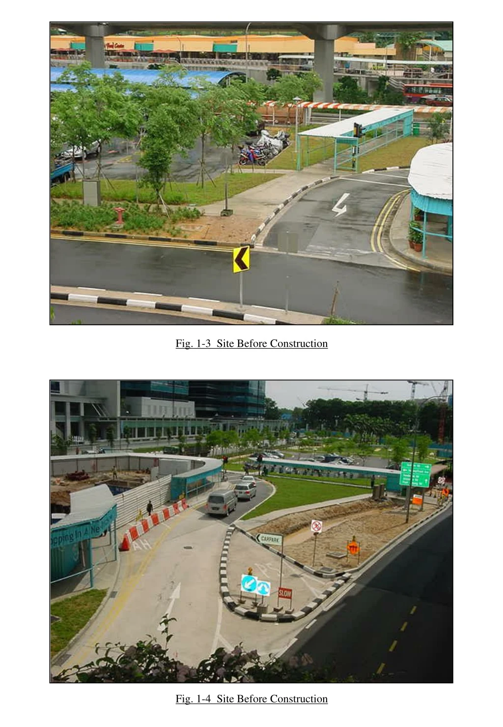
Fig. 1-3 Site Before Construction Fig. 1-4 Site Before Construction
Fig. 1-5 Site During Construction Fig. 1-6 Site During Construction
Soffit of Existing Overhead Carriageway Limited Headroom Fig. 1-7 Micropile Construction in areas of limited headroom Fig. 1-8 Micropile Construction Close To Existing Building
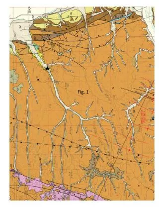
Proposed Overhead Bridge Fig. 1-9 Site Plan
Fig. 2-3 Trial Pit Location Fig. 2-4 Diversion Works of Existing Services Pipes
Fig. 2-5 Demolishing Existing Bus Bay Fig. 2-6 Diversion Works of Existing Drain
Fig. 3-2 Cement Grout Mixer Fig. 3-3 Cube Mould
Fig. 3-4 Main Reinforcement Fig. 3-5 Spiral Links
Fig. 3-6 PVC Spacers Fig. 3-7 Centraliser
Fig. 3-32 Mobilising micropiling equipment and machinery on site Fig. 3-33 Steel Casing With 2 Layers of Bitumen Membrane
Fig. 3-34 Steel Casing With 2 Layers of Bitumen Membrane Fig. 3-35 Installing Inner Steel Casing
Fig. 3-36 Measuring Tape for Borehole Depth Measurement Fig. 3-37 Drilling Rods
Fig. 3-38 Drilling Bit Fig. 3-39 Drilling of Soil by Wash Boring
Fig. 3-40 Drilling of Soil by Wash Boring Fig. 3-41 Drilling of Soil by Wash Boring
Fig. 3-42 Installing Main Reinforcement Into Borehole Fig. 3-43 Cleaning The Main Reinforcements By Water
Fig. 3-44 Removing The Plastic Cover of Threaded Rebars Fig. 3-45 Jointing Main Reinforcements
Fig. 3-46 Jointing The Main Reinforcements With Standard Coupler Fig. 3-47 Tightening The Reinforcement By Hand And Follow By Torque Wrench
Fig. 3-48 A Torque Wrench Fig. 3-49 Spiral Links Before Placing In Designed Spacing
Fig. 3-50 Placing The Spiral Links In Designed Spacing Fig. 3-51 Using Hydraulic Pump and Pump Sump To Remove Excess Water Into Water Tank
Fig. 3-52 Injecting Cement Grout Into The Borehole Fig. 3-53 Injecting Cement Grout Into The Borehole
Cement Grout Annular Space Filled With Bentonite Slurry Inner Casing Outer Casing Fig. 3-54 Micropile With Double Casing Debonding Inner Casing Outer Casing Fig. 3-55 Micropile With Double Casing Debonding
Fig. 3-56 Cutting Excessive Casing To Cut Off Level Fig. 3-57 Cutting Excessive Casing To Cut Off Level
Starter bars Formwork Fig. 3-59 Pile Cap Construction Fig. 3-60 Pile Cap Construction
Fig. 4-2 Probe, Pulley And Control Cable Fig. 4-3 Casing For Inclinometer
Fig. 4-4 Piezometer Fig. 4-5 Operating Principle
Fig. 4-6 Settlement Point S-16 Fig. 4-7 Settlement Point S-17
Fig. 4-8 Tilt Plate Mounted On the Column of Existing Overhead Carriageway Fig. 4-9 Tilt Plate Mounted On the Column of Existing Overhead Carriageway
Fig. 5-2 Pile Loading Test Preparation - Placing Concrete Block Fig. 5-3 Pile Loading Test Preparation - Placing Concrete Block
Fig. 5-4 Pile Loading Test Preparation - Hydraulic Jack, Scale Rule & Dial Gauge Hydraulic Jack Scale Rule Dial Gauge Fig. 5-5 Pile Loading Test Preparation - Hydraulic Jack, Scale Rule & Dial Gauge
Fig. 5-6 Complete Pile Loading Test Arrangement Fig. 5-7 Dumpy Level Set for Measuring The Settlement
Fig. 5-8 Jacking System & Measurement System Fig. 5-9 Pile Head Capped With Steel Plate