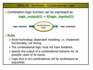
VERILOG: Synthesis - Combinational Logic
Combinational Logic. logic_inputs(t). logic_outputs(t). VERILOG: Synthesis - Combinational Logic. Combination logic function can be expressed as: logic_output(t) = f(logic_inputs(t)). Rules Avoid technology dependent modeling; i.e. implement functionality, not timing.

VERILOG: Synthesis - Combinational Logic
E N D
Presentation Transcript
Combinational Logic logic_inputs(t) logic_outputs(t) VERILOG: Synthesis - Combinational Logic • Combination logic function can be expressed as: logic_output(t) = f(logic_inputs(t)) • Rules • Avoid technology dependent modeling; i.e. implement functionality, not timing. • The combinational logic must not have feedback. • Specify the output of a combinational behavior for all possible cases of its inputs. • Logic that is not combinational will be synthesized as sequential.
Styles for Synthesizable Combinational Logic • Synthesizable combinational can have following styles • Netlist of gate instances and Verilog primitives (Fully structural) • Combinational UDP (Some tools) • Functions • Continuous Assignments • Behavioral statements • Tasks without event or delay control • Interconnected modules of the above
Synthesis of Combinational Logic – Gate Netlist • Synthesis tools further optimize a gate netlist specified in terms of Verilog primitives • Example: module or_nand_1 (enable, x1, x2, x3, x4, y); inputenable, x1, x2, x3, x4; outputy; wirew1, w2, w3; or(w1, x1, x2); or(w2, x3, x4); or(w3, x3, x4); // redundant nand(y, w1, w2, w3, enable); endmodule
Synthesis of Combinational Logic – Gate Netlist (cont.) • General Steps: • Logic gates are translated to Boolean equations. • The Boolean equations are optimized. • Optimized Boolean equations are covered by library gates. • Complex behavior that is modeled by gates is not mapped to complex library cells (e.g. adder, multiplier) • The user interface allows gate-level models to be preserved in synthesis.
Synthesis of Combinational Logic – Continuous Assignments Example: module or_nand_2 (enable, x1, x2, x3, x4, y); inputenable, x1, x2, x3, x4; outputy; assigny = !(enable & (x1 | x2) & (x3 | x4)); endmodule
Synthesis of Combinational Logic – Behavioral Style Example: module or_nand_3 (enable, x1, x2, x3, x4, y); inputenable, x1, x2, x3, x4; outputy; regy; always@(enable orx1 orx2 orx3 orx4) if(enable) y = !((x1 | x2) & (x3 | x4)); else y = 1; // operand is a constant. endmodule Note:Inputs to the behavior must be included in the event control expression, otherwise a latch will be inferred.
Synthesis of Combinational Logic – Functions Example: module or_nand_4 (enable, x1, x2, x3, x4, y); inputenable, x1, x2, x3, x4; outputy; assigny = or_nand(enable, x1, x2, x3, x4); functionor_nand; inputenable, x1, x2, x3, x4; begin or_nand = ~(enable & (x1 | x2) & (x3 | x4)); end endfunction endmodule
Synthesis of Combinational Logic – Tasks Example: module or_nand_5 (enable, x1, x2, x3, x4, y); inputenable, x1, x2, x3, x4; outputy; regy; always @(enable orx1orx2 orx3 orx4) or_nand (enable, x1, x2, x3c, x4); taskor_nand; inputenable, x1, x2, x3, x4; outputy; begin y = !(enable & (x1 | x2) & (x3 | x4)); end endtask endmodule
Construct to Avoid for Combinational Synthesis • Edge-dependent event control • Multiple event controls within the same behavior • Named events • Feedback loops • Procedural-continuous assignment containing event or delay control • fork ... join blocks • wait statements • External disable statements • Procedural loops with timing • Data dependent loops • Tasks with timing controls • Sequential UDPs
a[3:0] b[3:0] y[3:0] c[3:0] d[3:0] sel[1:0] Synthesis of Multiplexors • Conditional Operator module mux_4bits(y, a, b, c, d, sel); input[3:0] a, b, c, d; input[1:0] sel; output[3:0] y; assigny = (sel == 0) ? a : (sel == 1) ? b : (sel == 2) ? c : (sel == 3) ? d : 4'bx; endmodule
a[3:0] b[3:0] y[3:0] c[3:0] d[3:0] sel[1:0] Synthesis of Multiplexors (cont.) • CASE Statement module mux_4bits (y, a, b, c, d, sel); input[3:0] a, b, c, d; input[1:0] sel output[3:0] y; reg[3:0] y; always @(a or b or c or d or sel) case(sel) 0: y = a; 1: y = b; 2: y = c; 3: y = d; default:y = 4'bx; endcase endmodule
a[3:0] b[3:0] y[3:0] c[3:0] d[3:0] sel[1:0] Synthesis of Multiplexors (cont.) • if .. else Statement module mux_4bits (y, a, b, c, d, sel); input[3:0] a, b, c, d; input[1:0] sel output[3:0] y; reg[3:0] y; always @(a orb orc ord orsel) if(sel == 0) y = a; else if(sel == 1) y = b; else if(sel == 2) y = c; else if(sel == 3) y = d; elsey = 4'bx; endmodule Note: CASE statement and if/else statements are more preferred and recommended styles for inferring MUX
Unwanted Latches • Unintentional latches generally result from incomplete case statement or conditional branch • Example: case statement always @ (sel_a orsel_b ordata_a ordata_b) case({sel_a, sel_b}) 2'b10: y_out = data_a; 2'b01: y_out = data_b; endcase The latch is enabled by the "event or" of the cases under which assignment is explicitly made. e.g. ({sel_a, sel_b} == 2'b10) or ({sel_a, sel_b} == 2'b01)
Unwanted Latches (cont.) • Example: if .. else statement always @ (sel_a orsel_b ordata_a ordata_b) if({sel_a, sel_b} == 2’b10) y_out = data_a; else if ({sel_a, sel_b} == 2’b01) y_out = data_b;
Priority Logic • When the branching of a conditional (if) is not mutually exclusive, or when the branches of a case statement are not mutually exclusive, the synthesis tool will create a priority structure. • Example: module mux_4pri (y, a, b, c, d, sel_a, sel_b, sel_c); inputa, b, c, d, sel_a, sel_b, sel_c; outputy; regy; always @(sel_a orsel_b orsel_c ora orb orc ord) begin if(sel_a == 1) y = a; else if(sel_b == 0) y = b; else if(sel_c == 1) y = c; else y = d; end endmodule
VERILOG: Synthesis - Sequential Logic • General Rule: A variable will be synthesized as a flip-flop when its value is assigned synchronously with an edge of a signal. • Example: module D_reg4a (Data_in, clock, reset, Data_out); input[3:0] Data_in; inputclock, reset; output[3:0] Data_out; reg[3:0] Data_out; always @(posedge reset or posedge clock) if(reset == 1'b1) Data_out <= 4'b0; elseData_out <= Data_in; endmodule
Registered Combinational Logic • Combinational logic that is included in a synchronous behavior will be synthesized with registered output. • Example: module mux_reg (a, b, c, d, y, select, clock); input[7:0] a, b, c, d; output[7:0] y; input[1:0] select; reg[7:0] y; always @(posedge clock) case(select) 0: y <= a; // non-blocking 1: y <= b; // same result with = 2: y <= c; 3: y <= d; defaulty <= 8'bx; endcase endmodule
Verilog Shift Register • Shift register can be implemented knowing how the flip-flops are connected always @(posedge clock) begin if(reset == 1'b1)begin reg_a <= 1'b0; reg_b <= 1'b0; reg_c <= 1'b0; reg_d <= 1'b0; end elsebegin reg_a <= Shift_in; reg_b <= reg_a; reg_c <= reg_b; reg_d <= reg_c; end end
Verilog Shift Register • Shift register can be implemented using concatenation operation referencing the register outputs module Shift_reg4 (Data_out, Data_in, clock, reset); inputData_in, clock, reset; outputData_out; reg[3:0] Data_reg; assignData_out = Data_reg[0]; always @(negedge reset or posedge clock)begin if(reset == 1'b0) Data_reg <= 4'b0; elseData_reg <= {Data_in, Data_reg[3:1]}; end endmodule
Verilog Ripple Counter 4-bit Ripple Counter
Verilog Ripple Counter module ripple_counter (clock, toggle, reset, count); inputclock, toggle, reset; output[3:0] count; reg[3:0] count; wirec0, c1, c2; assignc0 = count[0], c1 = count[1], c2 = count[2]; always @(posedge reset or posedge clock) if(reset == 1'b1) count[0] <= 1'b0; else if(toggle == 1'b1) count[0] <= ~count[0]; always @(posedge reset or negedge c0) if (reset == 1'b1) count[1] <= 1'b0; else if(toggle == 1'b1) count[1] <= ~count[1]; always @(posedge reset or negedge c1) if(reset == 1'b1) count[2] <= 1'b0; else if(toggle == 1'b1) count[2] <= ~count[2]; always @(posedge reset or negedge c2) if(reset == 1'b1) count[3] <= 1'b0; else if(toggle == 1'b1) count[3] <= ~count[3]; endmodule Synthesis Result
Verilog Up/Down Counter Functional Specs. • Load counter with Data_in when load = 1 • Counter counts when counter_on = 1 • counts-up when count_up = 1 • Counts-down when count_up = 0
Verilog Up/Down Counter (cont.) module up_down_counter (clk, reset, load, count_up, counter_on, Data_in, Count); inputclk, reset, load, count_up, counter_on; input[2:0] Data_in; output[2:0] Count; reg[2:0] Count; always @(posedge reset or posedge clk) if(reset == 1'b1) Count = 3'b0; else if(load == 1'b1) Count = Data_in; else if(counter_on == 1'b1) begin if(count_up == 1'b1) Count = Count +1; elseCount = Count –1; end endmodule