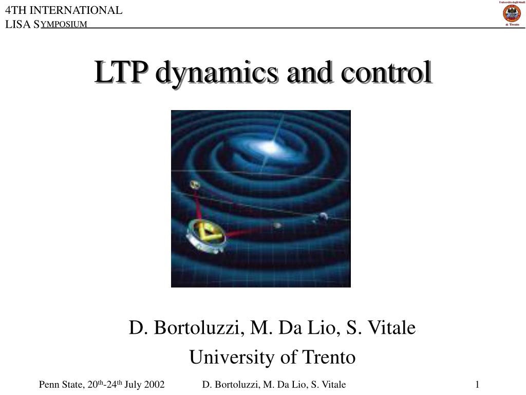
LTP dynamics and control D. Bortoluzzi, M. Da Lio, S. Vitale University of Trento D. Bortoluzzi, M. Da Lio, S. Vitale
The LTP basic mode of operation D. Bortoluzzi, M. Da Lio, S. Vitale
D. Bortoluzzi, M. Da Lio, S. Vitale
LTP is an autonomous dynamical system D. Bortoluzzi, M. Da Lio, S. Vitale
TM-S/C relative displacement Readout noise External forces on S/C suppressed by drag-free control loop Requirements given for S/C control D. Bortoluzzi, M. Da Lio, S. Vitale
LTP Multibody model • Defined frames • Inertial reference frame • Spacecraft body fixed reference frame • S/C-LTP mechanical interface reference frame • Optical bench body fixed reference frame • Electrode housings reference frames • Test masses body fixed reference frames • Coordinates • Spacecraft (Inertial Frame) • Test mass 1 (S/C frame) • Test mass 1 (EH frame) • … D. Bortoluzzi, M. Da Lio, S. Vitale
Distortions • Displacements of H1, H2 (readout references) frames due to distortions occurring: • A) within the spacecraft (S/C-mechanical • interface frame) • (in S/C frame) • B) within the LTP (mechanical interface frame- • optical bench frame-electrode housings frames) D. Bortoluzzi, M. Da Lio, S. Vitale
Forces and torques • Picture of forces • Fsc, Tsc: total force and torque (in SC frame) applied by LTP onto the S/C • fe, te: total force and torque of environmental origin on TMs • fLTP, tLTP: total force and torque on TMs originated within the LTP or the S/C • f12, t12: force and torque between TM1 and TM2 • fh, th: total force and torque on TMs caused by the interaction between TMs and their housings (it includes actuation force and torque) D. Bortoluzzi, M. Da Lio, S. Vitale
TM-S/C coupling TM-S/C relative displacement TM-EH relative displacement TM-EH relative displacement TM-EH relative displacement TM-EH coupling Stray forces capacitive actuation Mass matrix Inverse of mass matrix S/C motion TM-S/C space-independent coupling OB-S/C relative position TM-EH space-independent coupling Capacitive readout cross-talk Capacitive readout noise Optical readout cross-talk Optical readout noise Dynamics 1: test-masses Dynamics 2: reaction on spacecraft Readouts D. Bortoluzzi, M. Da Lio, S. Vitale
Matrices provided Symbolic form (for instance: inertia) Numeric form (for instance: stiffness & cross-talk) D. Bortoluzzi, M. Da Lio, S. Vitale
Noise D. Bortoluzzi, M. Da Lio, S. Vitale
Example: x(t) signal obtained from given x readout noise spectral density Example: force noise spectral density obtained from sampled signal D. Bortoluzzi, M. Da Lio, S. Vitale
D. Bortoluzzi, M. Da Lio, S. Vitale
Simulation results D. Bortoluzzi, M. Da Lio, S. Vitale
Simulation results D. Bortoluzzi, M. Da Lio, S. Vitale
10-10N/10-7 N/m 1 mm Low frequency suspension Compensating negative stiffness kp= 10-7 N/m and dc forces D. Bortoluzzi, M. Da Lio, S. Vitale
Actuation cross-talk Low frequency suspension laws matrix Capacitive readout Single input single output control laws D. Bortoluzzi, M. Da Lio, S. Vitale
Dc force compensation only D. Bortoluzzi, M. Da Lio, S. Vitale
+ TM stabilisation D. Bortoluzzi, M. Da Lio, S. Vitale
Optimised control Robust against knowledge of parameters D. Bortoluzzi, M. Da Lio, S. Vitale
h(s) x(s) y(s) Numerical implementation of control laws D. Bortoluzzi, M. Da Lio, S. Vitale
ARMA basic step D. Bortoluzzi, M. Da Lio, S. Vitale
Stiffer TM actuation needed for emergency TM motion after a force step 10-11 N Low frequency suspension control Numerical implementation of control is good Very long damping time D. Bortoluzzi, M. Da Lio, S. Vitale
Limits of the low-frequency actuation: • Low damping • Low maximum force Limit to stiffness Limit to maximum force Different operational mode (accelerometer mode) is defined in which larger maximum force can be exerted with larger stiffness (up to hardware limit) D. Bortoluzzi, M. Da Lio, S. Vitale
Caging command Charge measurement command Transfer functions parameters upload Threshold detector External command Ch1, ch2,… Poles, zeroes, gain DC force offsets Transfer functions selection SCIENCE MODE DC comp. a Channels combinator TM stabiliz a DC comp. b TM stabiliz b Fd1,…, Fd6 Suspension switch x1,…,x6 ACCELEROMETER MODE Suspension c Calibration parameters upload Low frequency sine wave Charge measurement dither Suspension d LARGE AMPLITUDE MODE TBC Capacitive actuation functional block diagram D. Bortoluzzi, M. Da Lio, S. Vitale
Caging command Charge measurement command Capacitive actuation functional block diagram Transfer functions parameters upload Threshold detector External command Ch1, ch2,… Poles, zeroes, gain DC force offsets Transfer functions selection SCIENCE MODE DC comp. a Channels combinator TM stabiliz a DC comp. b TM stabiliz b Fd1,…, Fd6 Suspension switch x1,…,x6 ACCELEROMETER MODE Suspension c Calibration parameters upload Low frequency sine wave Charge measurement dither Suspension d LARGE AMPLITUDE MODE TBC D. Bortoluzzi, M. Da Lio, S. Vitale Capacitive actuation functional block diagram
Caging command Charge measurement command Capacitive actuation functional block diagram Transfer functions parameters upload Threshold detector External command Ch1, ch2,… Poles, zeroes, gain DC force offsets Transfer functions selection SCIENCE MODE DC comp. a Channels combinator TM stabiliz a DC comp. b TM stabiliz b Fd1,…, Fd6 Suspension switch x1,…,x6 ACCELEROMETER MODE Suspension c Calibration parameters upload Low frequency sine wave Charge measurement dither Suspension d LARGE AMPLITUDE MODE TBC D. Bortoluzzi, M. Da Lio, S. Vitale Capacitive actuation functional block diagram
Accelerometer mode: high damping, large force TM motion after a force step 10-7 N Accelerometer mode control damping time shorter D. Bortoluzzi, M. Da Lio, S. Vitale
Accelerometer mode threshold TM moved towards EH center TM subjected to force step Passage to low frequency suspension law Transition to-from accelerometer mode requested to damp long term transitory Needs adjustment of long term behaviour TM motion arrested D. Bortoluzzi, M. Da Lio, S. Vitale
Dc-force dominate Low frequency suspension and accelerometer mode asyntotic behaviour must be the same to avoid overshoot at handover Adjust low frequency gain D. Bortoluzzi, M. Da Lio, S. Vitale
Switch Command Capacitive model equation parameters upload Carrier waveform parameters upload F to V conversion 2 Fd1,…, Fd6 V1,…, V12 Carrier waveform synthesis 3 Capacitive actuation 1 IS FEE DAC 4 V1(t)..V12(t) forces TM F to V conversion 2 Capacitive sensing Optical metrology ADC Switch Command x1,…,x6 ADC D. Bortoluzzi, M. Da Lio, S. Vitale
Summary: • LTP dynamics mathematical model • Capacitive actuation control laws: low frequency suspension and accelerometer mode • Noise models • Simulations results of a drag-free and attitude control system matching the requirements given D. Bortoluzzi, M. Da Lio, S. Vitale