Download
1 / 25
261 likes | 474 Vues
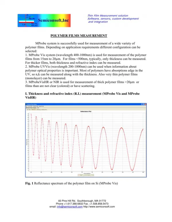
Piezo -effect and physics of CdS -based thin-film photovoltaics. Why high efficiency thin-film cells use CdS layer?. CdTe solar cell η=16.5%. CIGS solar cell η=19.9%. Piezo -electric and Pyro -electric effect of CdS have to be considered!. Victor Karpov

E N D
Piezo-effect and physics of CdS-based thin-film photovoltaics
Why high efficiency thin-film cells use CdS layer? CdTe solar cell η=16.5% CIGS solar cell η=19.9%
Piezo-electric and Pyro-electric effect of CdS have to be considered! Victor Karpov (Theoretical and Condensed Matter Physics) Professor of Physics, Department of Physics and Astronomy, University of Toledo Dr. of Science, 1986, Institute for Nuclear Physics, Academy of Science, Russia; Ph.D., 1979, Polytechnic University, Russia 2005Piezo-effect and physics of CdS-based thin-film photovoltaics 2007Piezo-photovoltaic coupling in CdS-based thin film photovoltaics 2007Pyroelectric coupling in thin film photovoltaics 2008Nanodipolephotovoltaics
Piezoelectricity Generate electric potential from Mechanical Stress Pyroelectricity Generate electric potential from Change in Temperature
Piezoelectricity in CdS originates from its Wurtzite structure Cd S Z-Axis
In a CdTe PV device, CdS layer is put under compression by lattice mismatch
5V voltage can be induced by piezoelectric effect (Polarization) = (Piezoelectric tensor) x (Stress)
Internal screening reduces piezoelectric voltage Carrier redistribution Surface charges 3) Random crystal orientation
External screening reduces piezoelectric voltage In conclusion, both the cases of fixed and equilibrium polarization are consistent with the available data, and neither can be ruled out at this point, both predicting the CdS barrier < 1 V Screening of a fixed polarization
Device operation Conventional device ,(c) Device with dipoles in CdS are modeled by AMPS
Device operation Gull-wing model can describe a number of experimental facts Pressure dependent PV performance CdS depletion Conductive CdS does not improve device CdS of certain morphology improves VOC Absence of carrier collection from CdS Negative quantum efficiency under blue illumination J-V crossover and light J-V rollover J-V crossover J-V rollover
Stress experiments for verifying theory Squeezing Bending Flexing Original Experiments
Result of experiment (CIGS cells) Reversible piezo-effect in both voltage and current Its magnitude is much lower than that of CdTe cells can be due to a thinness of the CdS layer
Nanodipolephotovoltaics : Aligned nanosize dipolescan generate built-in electric field Spontaneous polarizationcan takes place in electric field
Nanodipolephotovoltaics : CdSe Quantum dot Bandgap ~ 1.8eV Polyvinylcarbazole (PVK) is a photovoltaic polymer, which means that the bulk polymer — after being exposed to visible or ultraviolet light — becomes an electrical conductor
Research plan Deposition method Crystal structure Crystal orientation Grain size Piezoelectric effect Lattice strain Explanation of superior property CBD-CdS in CIGS PV cell by examination of piezoelectric effect Application : Development of vacuum-deposited CdS Development of alternative material
Research plan Development of new PV device Bended cell Stretched cell Epitaxially strained cell
Nanowire for photovoltaic use Idea #1 : Transfer process of silicon nanowires onto glass for PV cell use p-Si wafer p-Si wafer p-Si wafer p-Si wafer
Nanowire for photovoltaic use Idea #2
Nanowire for photovoltaic use Idea #2 : Hybrid piezoelectric-photovoltaic energy harvesting ZnO PVDF
20mm 15mm 16mm 17mm 18mm 19mm Front 20mm 15mm 16mm 17mm 18mm 19mm Back
Bilayer process for both good adhesion and conductivity High pressure deposition for 2 min Reduce pressure and adjust current Low pressure deposition for remaining time Experiment Low vacuum gauge could not read 1mTorr Pressure was adjusted by matching voltage to 330V Result Low deposition rate (target-substrate distance, target shape and size) It is known (110) oriented Mo result in high-efficiency (220/204) oriented CIGS Generally, BCC Mo structure have (110) preferred orientation because (110) planes are Closest-packed in bcc crystal with the lowest surface energy