Download
1 / 33
370 likes | 597 Vues
Development of Thin Film and Nanorod ZnO-Based LEDs and Sensors.

E N D
Development of Thin Film and Nanorod ZnO-Based LEDs and Sensors S. J. Pearton(1), W. T. Lim(1), J. S. Wright(1), R. Khanna(1), L. Voss(1), L. Stafford(1), L. C. Tien(1), H. S. Kim(1), D.P. Norton(1), J.-J. Chen(2), H.T. Wang(2), B.S. Kang(2), F. Ren(2), J. Jun (3), J. Lin(3), A.Osinsky(4) and A.Dabiran(4) (1) MSE, (2) Chem. Engin., (3) ECE, University of Florida, Gainesville, FL 32611 (4) SVT Associates, Eden Prairie, MN 55344 Supported in part by NSF DMR 0400416 (Verne Hess) and DOE DE-FC26-04NT42271 (Ryan Egidi)
Introduction GaNZnO Bandgap (eV)3.43.3 µe (cm2/V-sec)220200 µh (cm2/V-sec)105-50 me0.27mo0.24mo mh0.8mo0.59mo Exciton binding28 60 energy (meV) • Direct, wide bandgap • Bulk ZnO (n-type) commercially available • Grown on inexpensive (glass) substrates at low temperatures • High exciton binding energy • Heterojunction by substitution in Zn-site • Cd ~ 3.0 eV • Mg ~ 4.0 eV • Ease of synthesis of nanowires • Obstacle: good quality, reproducible p-type Potential Applications UV/Blue optoelectronics Transparent transistors Nanoscale detectors Spintronic devices
Zn(Mg,Cd)O alloys The ternary system CdO-ZnO-MgO covers a large bandgap range < Single quantum wells >
Zn0.95Cd0.05O/ZnO Heterojunction Band Offsets by XPS(samples grown by SVT-Andrei Osinsky) Samples grown by rf plasma assisted MBE 2.9 eV bandgap for ZnCdO XPS performed at UF, Charles Evans and Associates Conduction band offset 0.30 eV Valence band offset 0.17 eV
ZnCdO ZnO ECZnO ECZnCdO EC=0.30eV EgZnCdO=2.90 eV EgZnO =3.37eV EVZnCdO EVZnO EV=0.17eV (EV – EZn 2p3)ZnCdO =1020.85 eV (EV – EZn 2p3)ZnO =1020.83 eV EZn2p3ZnO EZn2p3ZnCdO Energy Band Diagram of Zn0.95Cd0.05O/ZnO Heterojunction • ΔEv=(EZn-2p-EV)thick ZnCdO-( EZn-2p-EV)ZnO- (EZn-2p-EZn-2p)ZnCdO/ZnO • ZnCdO is an attractive option as the narrow bandgap active region in ZnO-based heterojunction LEDs (ZnMgO band offset almost all in VB)
Ohmic Contacts to ZnCdO • The minimum contact resistivity • Ti/Au 2.3x10⁻⁴Ωcm2 at 450oC anneal • Ti/Al/Pt/Au1.6x10-4Ωcm2 at 500oC anneal • Severe degradation after 600oC anneal
Reference Reference 350oC 350oC 450oC 10 µm 450oC 600oC 600oC Optical Microscopy Images of Metal on ZnCdO As annealing temperature increases, metals start to form intermetallic compounds. Ti/Au to ZnCdO Ti/Al/Pt/Au to ZnCdO • Smoother morphology after annealing even at 600oC • Reacted appearance after 350oC • Ti/Au more thermally stable than Ti/Al/Pt/Au • More information: AES Depth profile
AES Depth Profile of Ti/Au to ZnCdO • Zn and Ti outdiffusion to the surface by 450oC • The formation of the TiOx interfacial region is evident after annealing improved contact resistance
AES Depth Profile of Ti/Al/Pt/Au to ZnCdO • Al outdiffusion to the surface by 450oC in the metallization scheme • Outdiffusion of Pt, Al, and Ti at higher anneal temperatures and oxidation of the Ti
TI/Au Ohmic Contact to Al-doped n-ZnO • The as-deposited contacts are ohmic with excellent specific contact resistivity of 2.4x10⁻⁷ Ω cm2 • Subsequent annealing produces a minimum value of 6x10⁻⁸ Ω cm2 after processing at 300oC • Carrier tunneling and additional annealing further reduces the specific contact resistance
Au Ti 800Å 200 Å 1 μm ZnO:Al Tunneling of Ti/Au Contact to Al-doped n-ZnO • Temperature range: 25~225oC • Independence of temperature • tunneling is the dominant current transport mechanism • The relation between the specific resistivity and doping concentration:
High selectivity Isotropic etch profile Ability to remove undesirable ions and contaminants from the wafer surface Ohmic ring Ohmic ring p-ZnO p-ZnMgO ZnO Photoresist n-ZnMgO n+-ZnO Film to be etched substrate Underlying Film Wet Chemical Etching Process involves either oxidation or reduction of semiconductor surface followed by removal of the soluble reaction product ZnO LED cross section structure Isotropic etch profile
Etching of ZnCdO (samples grown at SVT ) Using dilute HCl and H3PO4 mixtures Controllable etch rates in the range (<100 nm min-1) for mesa formation Solution temperature in the range of 25- 75oC The etch rate is diffusion-limited
100μm Selective Etching of ZnCdO over ZnO Optical microscopy minimum undercut Etch rate is independent of orientation The selectivity with HCl/H2O was over 30 The maximum selectivity with H3PO4 /H2O was ~15
Etching of ZnMgO Solution temperature in the range of 25-75oC The etch rate is diffusion-limited
Selective Etching of ZnMgO over ZnO The selectivity with HCl/H2O was over 250 The maximum selectivity with H3PO4/H2O was ~30
Site-selective growthof ZnO nanorods possible using a catalysis-driven molecular beam epitaxy method. Zn flux O2/O3 flux RF PLASMA RHEED SCREEN OZONE GENERATOR Ag catalyst particles OXYGEN O3/O2 Zn Zn ION GAUGE Mg Mg e-GUN EFFUSION CELL SUBSTRATE HEATER • Growth of ZnO on Ag-coated Si via MBE. • Nominal Ag film thickness: 20 ~ 200 Å. • (Coalesce into islands at growth temp.) • Oxygen source: ozone/oxygen mixture • Growth Temperature: 300°C ~ 600 °C.
Nanowires vs Zn, Mg pressures Radial heterostructured (Zn,Mg)O (Mg,Zn)O ZnO I II hexagonal core / sheath core / sheath cubic (Zn1-xMgx)O/(Zn1-xMgx)O (Zn1-xMgx)O / (Mg,Zn)O wurtzite st. rock salt st. hexa. / hexa. hexa. / cubic wurtzite / wurtzite wurtzite / rock salt st. Zn = 3 × 10⁻⁶ O3/O2 = 5 × 10⁻⁴ Mg = none Zn = 3 × 10⁻⁶ O3/O2 = 5 × 10⁻⁴ Mg = 2 × 10⁻⁷ Zn = 3 × 10⁻⁶ O3/O2 = 5 × 10⁻⁴ Mg = 4 × 10⁻⁷ Zn = 3 × 10⁻⁶ O3/O2 = 5 × 10⁻⁴ Mg = 8 × 10⁻⁷ [unit: mbar] Tg= 400C
Fabrication of ZnO nanowire device ZnO Nanowire Motivation Electrode (Al/Pt/Au) Al/Pt/Au -. Fundamental understanding of transport -. Nano sensors (UV, chemical, bio.) -. Nanoelectronics Insulator Structure of Nanodevice -. Electrode : Al/Pt/Au by sputtering -. Diameter of ZnO nanowire : 130 nm -. Channel Length : 3.5 m
Gate oxide ((Ce,Tb)MgAl11O19) Gate(Al/Pt/Au) Drain (Al/Pt/Au) Source (Al/Pt/Au) Nanowire Insulator (SiO2) Si Oxide Gate Source Drain Nanowire ZnO Nanorod MOS FET • Apply the stable oxide((Ce, Tb)MgAl11O19 ) for each device • Can be used as passive layer in gas, humidity, chemical sensor
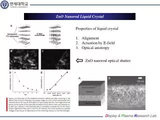
Microchannel Insulator pH Insulator (SiO2) Si pH sensor with gateless nanorod FET Nanowire electrode (Al/Pt/Au) 8.5 nS/ pH in the dark 20 nS/ pH underUV(365nm) Appl. Phys. Lett., 86, 112105 (2005)
ZnO currently used for detection of humidity, UV light and gas detection Easy to synthesize on a plethora of substrates Bio-safe characteristics Large chemically sensitive surface to volume ratio If coated with Pt or Pd, can increase device’s sensitivity to hydrogen High compatibility to microelectronic devices ZnO Nano-Rods for Hydogen Sensing Schematic of Multiple ZnO Nano-Rods Close-Up of Packaged ZnO Nano-Rod Sensor
Pt-ZnO Nanorod Electrode (Al/Pt/Au) Al/Pt/Au Insulator Single nanorod hydrogen gas sensor
Current status of ZnO LED research • 1. Nitrogen doping[ Tsukazaki et al. Nat. Mater. 4, 42 (2005) ] • Growth method • : L-MBE (repeated-temperature-modulation epitaxy) • Structure • : p-ZnO:N / i-ZnO / n-ZnO:Ga LED on a ScAlMgO4 substrate (c) Electroluminescence (a) Structure (b) Current-voltage
Current status of ZnO LED research • 2. Phosphorus doping [ Limet al. Adv. Mater. 18, 2720 (2006) ] • Growth method • : Sputtering system • Structure • : p-ZnO:P / n-ZnO:Ga LED on a sapphire substrate • : Mg0.1Zn0.9O energy barrier layer (a) Current-voltage (b) Electroluminescence
Current status of ZnO LED research • 3. Arsenic doping [ Ryu et al., Appl. Phys. Lett. 88, 241108 (2006) ] • Growth method • : Hybrid beam deposition (HBD) • Structure • : p-ZnO:As / active layer / ZnO substrate • : BeZnO/ZnO active layer (seven quantum wells) (b) Current-voltage (c) Electroluminescence (a) Structure
Au (80nm) Ni (20nm) N+ implanted ZnO (300nm) ZnO substrate Ti (20nm) Au (200nm) Device Fabrication Cermet: (0001) undoped, I grade n0=1017 cm-3; μe=190 cm2/V·s Proc. of SPIE, Vol.5941, 59410D-1(2005) • Implantation dose 1: 10keV, 2×1013 cm-2 dose 2: 30keV, 5×1013 cm-2 dose 3: 65keV, 9×1013 cm-2 dose 4: 140keV, 2.4×1014 cm-2 • Thermal activation (RTA, furnace; T=600~1000°C) • Backside metal: Ti/Au(20/200nm) • Front-side metal: Ni/Au(20/80nm)
Diode I-V Characteristics Leakage current~10-4A @ -6V Ideality factor~11
Device fabrication Light emission from ZnO pn homojunction device
Vertical ZnO NWs/PEDOT LEDNanowire Array The cross section schematic of ZnO nanowires LED
Summary Valence and conduction band offsets of the Zn0.95Cd0.05O/ZnO material system are 0.17 eV and 0.30 eV, respectively. In the ZnMgO, the band offset is mainly in the valence band Ohmic contacts fairly simple on n-and p-ZnO, but Schottky contacts are difficult (low barrier height, leaky). The etch selectivity of ZnCdO/ ZnO with HCl/H2O >30 Some rudimentary LEDs demonstrated by groups worldwide-need to show robust bandedge EL on cheap, large area substrates if there is any chance of finding a niche relative to the nitrides Functional nanowires with excellent structural and optical quality-many types of sensors demonstrated-Electrical transport properties of single ZnO nanowires, Pt/ZnO nanowire Schottky Diode, depletion-mode ZnO nanowire field-effect transistor, UV, pH, & gas sensor Lots of room to study transport/functionality in radial and longitudinal wires
Conclusions • Site-selective growth of ZnO nanowires using catalyst, Ag, by molecular Beam Epitaxy • Bimodal growth of cored ZnO/(Zn,Mg)O heterostructured nanowires. • Type I -. Core : Zn1-xMgxO (x < 0.02) , Hexagonal wurtzite structure -. Sheath : Zn1-xMgxO (x >> 0.02), Hexagonal wurtzite structure • Type II -. Core : Zn1-xMgxO (x < 0.02), Hexagonal wurtzite structure -. Sheath : (Mg,Zn)O, Cubic rock salt structure • (Mg,Zn)O nanowires having cubic rock salt structure • Nano-devices using ZnO nanowires • Electrical transport properties of single ZnO nanowire • Pt/ZnO nanowire Schottky Diode • Depletion-mode ZnO nanowire field-effect transistor • UV, pH, & gas sensor