Download
1 / 36
360 likes | 386 Vues
This document provides an update on the FEE (Front-End Electronics) status for X-ray transport, optics, and diagnostics. It includes information on the development schedule, sub-system status, key dates, and milestones.

E N D
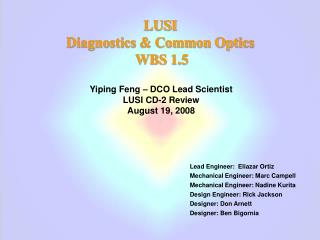
X Ray Transport, Optics, and Diagnostics: FEE Status Donn H. McMahon LCLS XTOD CAM DOE Review May 13-15, 2008 This work performed under the auspices of the U.S. Department of Energy by Lawrence Livermore National Laboratory under Contract DE-AC52-07NA27344. This work was performed in support of the LCLS project at SLAC.
Outline • XTOD Status • Development Schedule and Milestones (L3) • XTOD Plan • Sub-system Status • Key Dates • Summary
XTOD Scope: FEE Wall penetration Solid Attenuators Slit K Monochromator Collimators Wall penetration Thermal Sensor Fixed Mask Gas Attenuator Gas Detector Beam Direction Gas Detector Direct Imager (Scintillator) FEL Offset Mirror Systems
FY08/09 XTOD Plan • FYO8 • FDR, Procurements, Assemble/Integrated Test • Fast Shutter, Fixed Mask, Slit, Attenuators, Gas Detector • Total Energy, Direct Imager • FEE/NEH Mech & Vac – Wall -1 Shielding • SOMS Mirror substrates coating • Controls assembled/tested - FEE 1st half • Controls procured - FEE 2nd half, NEH, Tunnel, FEH • FDR, Procurements • FEE/NEH Mech & Vac – Beamlines+, Wall-2 & Shadow wall Shielding, Collimators • K-Monochromator, SOMS/HOMS Opto-Mechanical Systems, Pop-in Monitors • Install EBD components (Wall-1 assembly) • FY09 • Procurements • NEH Mech & Vac – Beamlines+, Collimators, Exclusion/Protection Zones • Tunnel Mech & Vac – Beamlines+ • Assemble/IntegratedTest, Ship to LCLS: (* Assembledtested in FY08) • [Fixed Mask, Slit, Attenuators, Gas Detector, Total Energy, Direct Imager ]* • K-Monochromator, SOMS/HOMS Opto-Mechanical Systems, Pop-in Monitors • FEE/NEH Mech & Vac - Beamlines, Wall-2 & Shadow wall Shielding, Collimators • Tunnel, FEH Mech & Vac • Corresponding FEE/NEH/XVTS/FEH Controls • Install all FEE, NEH, Tunnel, FEH components • Commissioning
XTOD Status as of 4.08 K-Monochromator Thermal Detector Solid Attenuators FEE Mechanical & Vacuum NEH Mechanical & Vacuum Fixed Mask X-Ray Tunnel Slit FEH Mechanical & Vacuum Gas Detector Gas Attenuator Direct Imager (Scintillator) • FEL Offset Mirror System Soft X-Ray Mirrors Soft X-Ray H/W Pop-In Cameras Hard X-Ray Mirrors Hard X-Ray H/W Key: Preliminary Design Review Complete Final Design Review Complete Installation Complete
XTOD Planned Status as of 4.09 K-Monochromator Thermal Detector Solid Attenuators FEE Mechanical & Vacuum NEH Mechanical & Vacuum Fixed Mask X-Ray Tunnel Slit FEH Mechanical & Vacuum Gas Detector Gas Attenuator Direct Imager (Scintillator) • FEL Offset Mirror System Soft X-Ray Mirrors Soft X-Ray H/W Pop-In Cameras Hard X-Ray Mirrors Hard X-Ray H/W Key: Preliminary Design Review Complete Final Design Review Complete Installation Complete
FEE Diagnostic Hardware Status • Fixed Mask / Slit • In house, Integrated testing • Attenuator • Under assembly • Gas Detectors • In house/integrating • Thermal Sensor • Vessel on order • Sensors in fabrication • Direct imager • Vessel on order • Cameras, scintillators, filters in house • K monochromator in final design • Pop-in Monitors ready for SCR • Controls • 4 of 5 FY08 FEE racks complete • FEE Vacuum Rack 75% • 98% of all other controls h/w received
N2 boil-off (surface) Gas Attenuator / Gas Detector / Solid Attenuator Gas detector Flow restrictor 4.5 meter long, high pressure N2 section Differential pumping sections separated by 4 mm apertures 4 mm diameter holes in B4C disks allow 880 mm (FWHM), 827 eV FEL to pass unobstructed Solid attenuators N2 Gas inlet Green line carries exhaust to surface Gas detector System being assembled now
Gas Detectors Photomultiplier Tube Avalanche Photodiode Pressure sensors Magnet Coils UV quiet liner Gas inlet / flow control
Direct Imager Scintillation Camera Single shot measurement of shape, centroid, and pulse energy Cameras and scintillators here, Vacuum system on order NFOV Camera (12 x 12 mm) WFOV Camera (60 x 60 mm) Scintillators YAG:Ce
Thermal Sensor provides calibrated measurement of FEL pulse energy Measures FEL energy deposition through temperature rise Cu heat sink Thermistors Nd0.66Sr0.33MnO3 (On back of substrate) Sensor Temperature Rise FEL pulse [K] 0.5 mm Si substrate t = 0 t = 0.25 ms t = 0.1 ms Thermal diffusion of FEL energy Sensors are being fabricated, vacuum system on order
Thermal sensor, theory (blue) and experiment (red) Prompt non-thermal pulse Thermal pulse Temperature, K
Thermal sensor measurements vs. calibration laser energy Thermal sensor measured energy, micro J Calibration laser energy, micro J
Sensor Suite Reduces, averages, and slows down athermal signal • Complementary sensors: • Single pulse vs averaging • Single pixel vs position-sensitive 5-pixel • 1 mm2 vs 4 mm2 sensor • Backup sensors • Sensor stage: • 8 sensor positions • 16 pixels total • ± 1/2” left-right motion • 3 µm steps in x and z • 8” up-down motion • 5 µm steps in y • Likely addition • Radiation shielding Attachment to pulse tube and XYZ-stage Weak thermal link Heater stage for T regulation Two 25-pin connectors Fiduciary mark (crosshair) 8 sensor positions: 6 single pixel sensors 2 arrays with spatial resolution
K monochromator in final design Beam direction Quad cell detector - MDC stepper driven x, y stage Reticule - MDC stepper driven x, y stage • Crystal pointing (yaw) • - cam driven sine plate Crystal insertion/retraction - Only two positions required - Thomson stepper motor driven linear actuator • Crystal, periscope, & tuning assembly is on the critical path • Will demonstrate transmission at SSRL in November
Summary of measurements on SOMS # 1, 2 substrates vs. LCLS SOMS Specifications • SOMS #1 mirror substrate appears to have rather uniform finish among all locations measured. • The surface topography from both AFM and Zygo measurements shows an combination of long-range polishing marks in two slightly different directions. The morphology is not similar to that measured on earlier, smaller size coupons SOMS #1 • SOMS #2 mirror substrate appears to have rather uniform finish among all locations measured • The surface topography from both AFM and Zygo measurements appears similar to that measured on earlier, smaller size coupons SOMS #2
InSync Serial Number P07112_1 (SOMS 1) The first SOMS mirror meets its specification for long spatial scale curvature • Total budget for long scale curvature is < 20 nm tangential, < 5 nm sagittal* • - limits intensity asymmetry due to reflections to < 10% • Allocation to fabrication errors was 10 nm tangential, 4 nm sagittal • - contour plot shows SOMS 1 meets this requirement Contour plot with 10x175 mm2 mask 9nm Color map of 250x50 mm2 SOMS 1 figure Figure, nm 0 Sagittal axis, mm Tangential axis, mm 10 0 175 * See detailed figure budget in ESD 1.5-122, “HOMS & SOMS Opto-mechanical Design”
HOMS/SOMS design is nearly complete: mirror figure and pointing requirements are being demonstrated on prototypes Mirror & Mount Chamber & mirror Pointing & centering Installation alignment struts 1.4 m Tunable bending force Support Pedestal Si Mirror Invar mount Chin guard
4 Mirror figure budgets were established by analysis, and confirmed by experiment • In-situ HOMS • mirror bender • Predicted by analysis HOMS Total • Measured response to mirror • bending force • Coating • Mounting • Thermal • Gravity Calculated figure, 2.7 lb bending force 270X15 mm2 mask 12” Zygo FOV
Demonstrations of mirror pointing resolution and stability < 100 nano-radians will be completed this summer • Resolution, linearity, and backlash requirements are met • - capacitance sensors measure nm scale motion • Pointing vibration stability has been measured • - proved a stiffer pedestal was needed • The next challenge: demonstrating thermal stability • - response to temperature has been measured • - mirror systems will be housed in thermal enclosures controlled within < 0.03 C Theoretical From amplified ground motion
Summary • Reasonable schedule and tight budget for FY08. • XTOD will have completed all system designs and assembled and tested the 1st half of the FEE instruments by FY08 end. • Nearly all interfaces are or have been addressed. • FY09 schedule is predicated on the ability to procure systems using Stanford University funds. • Installation schedule are reasonable assuming FY09 procurements go as planned.
XTOD FY08 Budget Summary • XTOD Budget Concerns • FY08 is highly constrained and success oriented plan • Controls fabrication/integration, total energy final sensor production, FEL Offset prototype, and Imager design primary cost variance contributors. ($200K total variance) • End of year carry over unlikely LLNL Direct Costs
2-D Power Spectral Density(PSD) analysis of surface metrology on SOMS#1 and SOMS#2 Si test substrates
XTOD Installation Schedule FEE 1st Light (5/09) NEH 1st Light (7/09) FEH 1st Light (1/10)
XTOD Interfaces • XTOD to Conventional Facilities • Power – FEE Panels to XTOD racks • Wall-1,-2 penetrations • Controls cable plant • Compressed air lines • Nitrogen supply lines • XTOD to Linac Systems • Fast valve – location, sensors, and electronics • XTOD to LUSI • NEH Vacuum interfaces • Tunnel Vacuum interfaces • XTOD to XES • PPS locations • K-Monochromator crystals • NEH radiation shielding • Reviewed/In Process • To be Reviewed