Download
1 / 46
460 likes | 475 Vues
This study presents numerical and experimental investigations of thin liquid film stability on porous wetted walls, with a focus on the effects of injection velocity, initial film thickness, evaporation/condensation, and droplet detachment time. The results provide insights into the protection of walls in liquid injection systems.

E N D
NUMERICAL AND EXPERIMENTAL STUDIES OF THIN-LIQUID-FILM WALL PROTECTION SCHEMES S.I. ABDEL-KHALIK AND M. YODA G. W. Woodruff School of Mechanical Engineering Atlanta, GA 30332-0405 USA
Primary Contributors • Numerical Simulation of Porous Downward Facing Wetted Walls • Seungwon Shin & Damir Juric • Experimental Investigation of Liquid Film Stability on Porous Wetted Walls • Fahd Abdelall & Dennis Sadowski • Experimental Study of Forced Thin Liquid Film Flow on Downward Facing Surfaces • J. Anderson, S. Durbin & D. Sadowski
Numerical Simulation of Porous Wetted Walls (Follow up on Madison ARIES Meeting) • Minimum Film Thickness Prior to Droplet Detachment • Effect of Evaporation/Condensation on • Detachment Time • Detached Droplet Diameter • Minimum Film Thickness
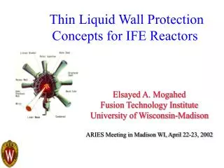
Numerical Simulation of Porous Wetted Walls Problem Definition Liquid Injection X-rays and Ions IFE Reactor Chamber (Prometheus-L)
Quantify effects of • injection velocity win • initial film thickness zo • Initial perturbation geometry & mode number • inclination angle • Evaporation & Condensation at the interface on • Droplet detachment time • Equivalent droplet diameter • Minimum film thickness prior to detachment Numerical Simulation of Porous Wetted Walls Summary of Results
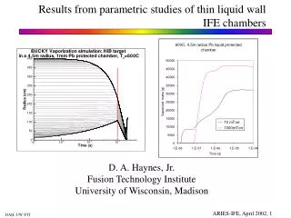
Numerical Simulation of Porous Wetted Walls Evolution of Minimum Film Thickness (High Injection/Thin Films) Nondimensional Initial Thickness, zo*=0.1 Nondimensional Injection velocity, win*=0.05 Nondimensional Minimum Thickness Drop Detachment Minimum Thickness Nondimensional Time
zo Numerical Simulation of Porous Wetted Walls Effect of Initial Perturbation • Initial Perturbation Geometries Sinusoidal s Random zo Saddle zo s
Numerical Simulation of Porous Wetted Walls Effect of Initial Perturbation Pb at 700K Detachment time (s) Sinusoidal zo, s= 0.5 mm win = 1 mm/s 0.31 Random win = 1 mm/s 0.38 Saddle win = 1 mm/s 0.30
Numerical Simulation of Porous Wetted Walls Effect of Liquid Injection Velocity win (s) win = 0 mm/s zo, s = 0.2 mm 0.48 win = 0.1 mm/s zo, s = 0.2 mm 0.47 win = 1 mm/s zo, s = 0.2 mm 0.43 win = 10 mm/s zo, s = 0.2 mm 0.42
Numerical Simulation of Porous Wetted Walls Evolution of Minimum Film Thickness (High Injection/Thick Films) Nondimensional Initial Thickness, zo*=0.5 Nondimensional Injection velocity, win*=0.05 Nondimensional Minimum Thickness Drop Detachment Minimum Thickness Nondimensional Time
Numerical Simulation of Porous Wetted Walls Evolution of Minimum Film Thickness (Low Injection/Thin Films) Nondimensional Initial Thickness, zo*=0.1 Nondimensional Injection velocity, win*=0.01 Nondimensional Minimum Thickness Drop Detachment Minimum Thickness Nondimensional Time
Numerical Simulation of Porous Wetted Walls Evolution of Minimum Film Thickness (Low Injection/Thick Films) Nondimensional Initial Thickness, zo*=0.5 Nondimensional Injection velocity, win*=0.01 Nondimensional Minimum Thickness Minimum Thickness Drop Detachment Nondimensional Time
Numerical Simulation of Porous Wetted Walls Non-Dimensional Representation • Nondimensional Momentum Equation where , , , , ,
Numerical Simulation of Porous Wetted Walls Minimum Film Thickness
Numerical Simulation of Porous Wetted Walls Minimum Film Thickness
Numerical Simulation of Porous Wetted Walls Minimum Film Thickness
Numerical Simulation of Porous Wetted Walls Evaporation/Condensation at the Interface • Nondimensional Mass Conservation where
Numerical Simulation of Porous Wetted Walls Evaporation/Condensation at the Interface • Interface Advancement
Water Lead Lithium Flibe T (K) 293 323 700 800 523 723 773 873 973 l (mm) 2.73 2.65 2.14 2.12 8.25 7.99 3.35 3.22 3.17 U0(mm/s) 163.5 161.2 144.7 144.2 284.4 280.0 181.4 177.8 176.4 t0 (ms) 16.7 16.4 14.8 14.7 29.0 28.6 18.5 18.1 18.0 Re 445 771.2 1618 1831 1546 1775 81.80 130.8 195.3 Numerical Simulation of Porous Wetted Walls Non-Dimensional Parameters For Various Coolants
Numerical Simulation of Porous Wetted Walls Effect of Evaporation/Condensation at Interface • zo*=0.1, win*=0.01, Re=2000 mf*=-0.005 mf*=0.0 mf*=0.01 (Evaporation) (Condensation) *=31.35 *=27.69 *=25.90
Numerical Simulation of Porous Wetted Walls Effect of Evaporation/Condensation at Interface • zo*=0.1, win*=0.05, Re=2000 mf*=-0.005 mf*=0.0 mf*=0.01 (Evaporation) (Condensation) *=25.69 *=25.13 *=25.74
Numerical Simulation of Porous Wetted Walls Effect of Evaporation/Condensation at Interface • zo*=0.5, win*=0.01, Re=2000 mf*=-0.005 mf*=0.0 mf*=0.01 (Evaporation) (Condensation) *=15.94 *=16.14 *=16.84
Numerical Simulation of Porous Wetted Walls Effect of Evaporation/Condensation at Interface • zo*=0.5, win*=0.05, Re=2000 mf*=-0.005 mf*=0.0 mf*=0.01 (Evaporation) (Condensation) *=17.11 *=16.94 *=17.83
Numerical Simulation of Porous Wetted Walls Non-Dimensional Results -- Detachment Time Different Evaporation/Condensation mf* Values
Numerical Simulation of Porous Wetted Walls Non-Dimensional Results -- Detachment Time Different Evaporation/Condensation mf* Values
Numerical Simulation of Porous Wetted Walls Non-Dimensional Results -- Detachment Time Different Evaporation/Condensation mf* Values
Numerical Simulation of Porous Wetted Walls Non-Dimensional Results -- Detachment “Diameter” Different Evaporation/Condensation mf* Values
Numerical Simulation of Porous Wetted Walls Non-Dimensional Results -- Detachment “Diameter” Different Evaporation/Condensation mf* Values
Numerical Simulation of Porous Wetted Walls Non-Dimensional Results -- Detachment “Diameter” Different Evaporation/Condensation mf* Values
Numerical Simulation of Porous Wetted Walls Non-Dimensional Results – Minimum Film Thickness Different Evaporation/Condensation mf* Values
Numerical Simulation of Porous Wetted Walls Non-Dimensional Results – Minimum Film Thickness Different Evaporation/Condensation mf* Values
Numerical Simulation of Porous Wetted Walls Non-Dimensional Results – Minimum Film Thickness Different Evaporation/Condensation mf* Values
CONCLUSIONS • Generalized charts have been developed to allow quantitative evaluation of effects of various operating and design variables on system performance • Identify “design windows” for successful operation of the wetted wall concept • Experimental investigation to validate numerical results over desired parameter range underway (isothermal conditions)
Problem Definition First Wall Injection Point Detachment Distance xd X-rays and Ions Liquid Film/Sheet IFE chamber (Prometheus)
Objectives • Determine “design windows” for high-speed liquid films proposed for thin liquid protection of IFE reactor chamber first wall • Wall protection issues (in the absence of film dryout) • Detachment of film from first wall • Ejection of drops from film free surface • Downward-facing surfaces at top of chamber: greatest gravitational impact on detachment • Implementation issues • How does film spread from injection point? • How does film flow around obstructions (e.g. beam ports)? 2 mm nozzle 17 GPM 10.7 m/s 10o inclination Re = 20000 2 mm nozzle 17 GPM 10.7 m/s 10o inclination Re = 20000
Experimental Apparatus A Glass plate (1.52 0.40 m) B Liquid film C Splash guard D Trough (1250 L) E Pump inlet w/ filter F Pump G Flowmeter H Flow metering valve I Long-radius elbow J Flexible connector K Flow straightener M L I Adjustable angle J K x A z B H gcos g G C L Film nozzle M Support frame D E F
Experimental Parameters • Independent Variables • Film nozzle exit dimension = 0.1–0.2 cm • Film nozzle exit average speed U0 = 1.9 – 11.4 m/s • Jet injection angle = 0°, 10° and 30° • Surface inclination angle ( = ) • DependentVariables • Film width and thickness W(x), t(x) • Detachment distance xd • Location for drop formation on free surface
1.5 mm nozzle 13 GPM 10.9 m/s 10° inclination Re = 15000 1.5 mm nozzle 13 GPM 10.9 m/s 10° inclination Re = 15000 Dimensionless Groups • Reynolds number Re = U0 / = 3700–21,000 • Froude number Fr = U0 /(gcos ) = 15–115 • Only group involving • Weber number We = U02 / = 100–3200 • Film nozzle aspect ratio AR = (5 cm)/ = 25–50 • Fluid properties (water at 17–19°C into air at patm) • Kinematic viscosity = 1.06 10–6 m2/s • Density = 999 kg/m3 • Surface tension = 0.073 N/m
xd Detachment Distance xd • xd = distance along plate from nozzle exit where film detaches at plate surface 2 mm nozzle 17 GPM 10.7 m/s 10o inclination Re = 20000 • Instantaneousdetachment distance xd varies by up to 2 cm reported xd values average of 20 independent realizations 125.4 cm 127.6 cm 128.9 cm • Typical images (8 ms exp.) of liquid film over a few seconds: = 10°, Re = 8600, = 0.1 cm (A) [ruler in inches] • xd = 127.5 cm
= 0 = 10 = 30 xd: Fr Effects • xd / as Fr • xd /as • Growth ratesimilar for all cases (except at low Fr) • Account for different initial conditions with “virtual origin”? = 0.1 cm xd / = 0.15 cm = 0.2 cm Fr
y 2 mm nozzle 13 GPM 5 cm 8.2 m/s 10° inclination Re = 15000 x 2 mm nozzle W(x) 13 GPM 8.2 m/s 10° inclination Re = 15000 Average Film Width W(x) • Initially, film spreads after leaving nozzle (transition from no-slip to free surface at lower surface): “near-field” region • Farther downstream, film thickens (due to gravitational and surface tension effects) and detaches: “far-field” region • Since mass/vol. flux constant at every x location, W must decrease • Does W decrease before detachment? • W(x) measured from above (viewed through plate) • = 0.1 cm; = 30; Re = 7200; Fr = 81
= 0 = 10 = 30 W(x): Effects • = 0.2 cm (C) • Re = 18,000 • W independent of for x/ < 400 (near-field) • W as for x/ > 400 (far-field) • xc/ < xd/ for all cases Wc/W0 3.6 W/W0 xd/ xc/ 400 x/
Re = 7,500 Re = 12,400 Re = 18,600 W(x):Re Effects • = 0.2 cm (C) • = 30 • W independent of Re for x/ < 400 (near-field) • W independent of Re at high Re? • xc/ < xd/ in all cases Wc/W0 3.6 W/W0 xd/ xc/ 400 x/
Summary • Initial Observations • Detachment distance xd • Fr most important parameter for detachment distance xd • For high-speed films, consistent growth rate in xd / • Virtual origin to compensate for initial conditions • Film width (y-dimension) W • Maximum W 4–5 times initial value • Near-field (x < xc< xd): W dominated by initial conditions • Far-field (x > xc): most important parameter for W • Characteristic film width Wc = W(xc) • most important parameter for Wc • For high-speed films, Wc independent of Fr, Re and
Future Work • Determine “design windows” for high-speed liquid films proposed for thin liquid protection of IFE reactor chamber first wall • Wall protection issues (in the absence of film dryout) • Detachment of film from first wall • Ejection of drops from film free surface • Implementation issues • How does film spread from injection point? • How does film flow around obstructions (e.g. beam ports)?
1.5 mm nozzle 10 GPM 8.4 m/s 10° inclination Re = 11500 1.5 mm nozzle 10 GPM 8.4 m/s 10° inclination Re = 11500 Drop Ejection from Free Surface • Drops ejected from film free surface upstreamof detachment • Major issue for first wall protection: minimize drops in chamber