GRAPHIC COMMUNICATION
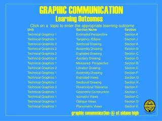
GRAPHIC COMMUNICATION. TECHNICAL GRAPHICS 2. INFORMATION SHEETS. UNIT SECTION NAME SECTION. Technical Graphics 2 Sectional Drawing Section A. Technical Graphics 2 Auxiliary Drawing Section D. Technical Graphics 2 Location Drawing Section E.

GRAPHIC COMMUNICATION
E N D
Presentation Transcript
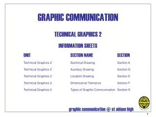
GRAPHIC COMMUNICATION TECHNICAL GRAPHICS 2 INFORMATION SHEETS UNIT SECTION NAME SECTION Technical Graphics 2 Sectional Drawing Section A Technical Graphics 2 Auxiliary Drawing Section D Technical Graphics 2 Location Drawing Section E Technical Graphics 2 Dimensional Tolerance Section F Technical Graphics 2 Types of Graphic Communication Section K
ORTHOGRAHIC PROJECTION – SECTIONAL VIEWS Cutting planes should be indicated by long chain lines, thickened at the ends and at changes of direction, thin lines elsewhere, and should be designated by capital letters. the direction of viewing is shown by arrows resting on the cutting line. Return to main page
ORTHOGRAHIC PROJECTION – SECTIONAL VIEWS Exceptions Sections Engineering details that do not show hatching when sectioned. Nuts and bolts Studs Screws Shafts Webs Ball bearings and ball races Roller bearings and other roller races Keys Pins Sectioning is a process which should be used only to simplify or clarify a drawing. There are some engineering details that, if sectioned, loose their identity or would create a wrong impression and these items are never sectioned. A list of these items is shown opposite. For further information refer to: BSI PP7308 Engineering Drawing Practice for Schools and Colleges. Second Revision 1986. Return to main page
In general, sections and sectional views should be hatched but hatching is often omitted in industry to save time and money. It is normal to use hatching in British Standards so it is used throughout this course. Hatching is drawn with type B lines, equally spaced at a well defined angle. In this course the angle of hatching lines is 45°. Spacing between hatching lines should preferably be not less than 4mm apart. However, when hatching very small areas this spacing should be reduced but never less than 1mm. When hatching separated areas of a single component the hatching lines should be in the same direction and with the same spacing (see figure (a)). Where different sectioned parts meet on an assembly drawing, the direction of hatching should normally be reversed and staggered (see figure (b)). In cases where hatching on adjacent parts must be at the same angle the lines should be staggered and may be more closely spaced (see figure (c)). Hatching of large areas may be limited to that part of the area which touch adjacent parts, or the outline of the large part (see figure (d)). Thin material in section may be filled in, in preference to showing the material thickness out of scale and hatched. When adjacent parts are thus shown a clear space of not less than 1mm should be left between them (see figure (e)). ORTHOGRAHIC PROJECTION – SECTIONAL VIEWS Hatching (a) Hatching separate areas. (b) Hatching adjacent parts. (c) Hatching separated areas and adjacent parts. (d) Hatching large areas. (e) Section through thin material. Return to main page
ORTHOGRAHIC PROJECTION – SUPPLEMENTARY VIEWS Auxiliary Elevation Construction Auxiliary Plan Construction 1. Project from the plan, at the required angle (back towards the direction of viewing, arrow A), where two or more lines meet. 2. Draw a datumline at right angles to the projection lines. (the ground line) 3. Transfer the heights from the common datum on the elevation to the appropriate projection line on the new view. 4. Complete the view by firming up seen edges using bold linetype. 1. Project from the elevation all the points from where two or more lines meet, (each corner), at the correct angle, (back towards the viewpoint, arrow A). 2. Draw the datum (ground line) at right angles to the projection lines. 3. Transfer the widths from the common datum on the plan onto the appropriate projection line in the new view. 4. Complete the view by firming up seen edges using bold linetype. Return to main page
LOCATION DRAWING Introduction Building drawings are produced to give information to a variety of professional people who are involved in checking that the design of a particular building or structure is in accordance with local planning conditions, and to those builders/developers who have the contracts for erecting the building or structure. Many different types of drawings are required in a building project. Three of the main drawings that make up the project set of drawings are the: Block Plan (sometimes referred to as the Site Location Drawing), the Site Plan and the Location Plan(sometimes referred to as the Building Plan). Block Plan (Site Location Drawing) This type of drawing is made to enable the exact location of a construction project to be defined in relation to its surroundings. This information is generally taken from an Ordinance Survey map and would commonly be drawn to a scale of 1:1250. This drawing will include details such as roads and streets in the immediate area, as well as their names, field boundaries, the outline of other buildings in the area and the direction of north. The main feature will be the outline plan of the proposed building within the boundary of the site. Note: 1. The outline of the plan of the building and the site boundary are drawn with thick lines. 2. The plan of the building is shaded using hatching lines. 3. Existing buildings have medium line thickness. 4. All other lines are thin lines. Block Plan 1:1250 Symbols and Abbreviations Points North Building in question Road Existing trees New trees (planted) Return to main page
LOCATION DRAWING Site Plan This type of drawing is made to show the exact position of a building within its site boundaries. This information shows the general layout of the site in relation to its immediate surroundings. Information generally shown on a site plan includes: 1. The outline plan of the building drawn in thick lines, all other lines are thin. 2. The dimensions give the exact position that the building is to occupy within the site. 3. Drainage systems are shown. 4. North is indicated 5. Roads adjoining the site are shown. 6. Driveway and footpaths are shown. Suitable scales for site plans are: 1:500 1:200 Site Plan 1:200 Symbols and Abbreviations Basic dimension (arrow heads at 45o) Manhole (soil) Manhole (surface water) Inside diameter Rainwater pipe Return to main page
LOCATION DRAWING Location Plan (Building Plan) This type of drawing is made to show the general arrangements of the building showing the interior. Rooms, stairs windows, doors, cupboards etc. are shown. If the purpose of this drawing is for showing the layout of space only, you may not see dimensions. You may see on occasion construction details of the building. Suitable scales for location plans are: 1:200 1:100 1:50 Location Plan Return to main page
ORTHOGRAHIC PROJECTION – DIMENSIONAL TOLERANCING Introduction British Standards are accepted as national guidelines in the industrial and commercial world. They define standards for technical criteria, manufacturing, and health and safety. British Standards assist in the reduction of unnecessary product variety, simplify and rationalise manufacturing processes and encourage interchange ability. They also make communication between professional people effective, since everybody can speak the same technical language. The topic tolerancinghas a very important part to play where British standards are concerned. What is a Dimensional tolerance? When manufacturing or constructing an item it is virtually impossible to achieve precisely the required size of the item. The error permissible in manufacture is called the tolerance - this is normally given on the drawing of the item. Tolerances which affect the size of an object or features on it are referred to as dimensional tolerances. They are also used to tolerance the size of locating features on an item or one item in relation to another. For example, the required length (or basic length) of part of a plastic pen clip, shown opposite, is 10mm. This size could vary, however, between 9.5mm and 10.5mm and still fit in the slot provided for it on the pen. A tolerance of 1mm, normally stated as ± 0.5mm, could therefore be applied to this dimension without affecting the function of the part. The length of this part of the clip could then be manufactured to any size between 9.5mm and 10.5mm and still be acceptable. Part of Plastic Pen Clip Return to main page
ORTHOGRAHIC PROJECTION – DIMENSIONAL TOLERANCING The Need for Dimensional Tolerances In a manufacturing or construction situation it is never possible to make an item to a precise dimension with absolute accuracy due to inaccuracies introduced through the manufacturing and construction process. This would not be a major problem if: i. each part did not interface or interact with any other part; or ii. the time and resources were available to further work each part until it interfaced as desired with mating parts. In reality these conditions are rarely met, or are they desirable. Modern technological advancement, mass production and the drive towards ever higher levels of productivity has led to increased demand for manufacturing accuracy. This can only be achieved through the appropriate use of tolerances. For example the accuracy with which a door hinge is manufactured will affect the ease of movement of the hinge - in other words it can be too tight or too slack. By specifying appropriate dimensional tolerances for the hinge the "feel" of the hinge can be controlled without requiring time consuming fitting and adjustment - parts not made to the required tolerances either being rejected as scrap or reworked. The European aerospace industry provides excellent examples of how technological and political progress has dictated an ever increasing need for accuracy. The Airbus, for example, is made of parts (wings, fuselage, tail section etc) made in various European countries before being shipped to France for assembly. Without tolerances the successful assembly of such a complex piece of machinery would not be possible. There is a similar need for tolerances in the construction industry, for example large power station cooling towers 100m or so in diameter, may have a shell thickness of only 100 or 120mm. Obviously very careful attention must be made to tolerances to ensure successful construction. On the other hand building tolerances are sometimes specified to allow for adjustment during construction, especially when the precise size of a mating part is not known - for example when a new building is being erected against the party wall of an existing house, the latter may not be plumb or square. Return to main page
ORTHOGRAHIC PROJECTION – DIMENSIONAL TOLERANCING The Use of Dimensional Tolerances. Tolerances are used in both the engineering and construction industries to specify limits on sizes and location on products as diverse as motorway flyovers, oil tankers, motor cars and digital watches. Tolerancing information is normally provided on manufacturing and construction drawings. It may be applied to: i. dimensions on single part manufacturing and construction drawings providing the maximum permissible variation of :- a. size of the item and features on it, and b. location of features, such as hole centres; ii. dimensions on assembly drawings giving the maximum permissible variation of dimensions of assembled components. Note-only dimensions crucial to the assembly and functionality of the assembled item are normally shown on assembly drawings. iii. dimensions on site and floor plans giving the maximum permissible variation in size and location of features. In practice, all dimensions on manufacturing and construction drawings are subject to tolerances. A distinction must be made, however, between functional and non functional dimensions which affects how and/or whether the tolerance is represented on a drawing. Functional dimensions are those which affect directly the functionality and interchange ability of parts e.g., the diameter of a bicycle seat pin which must fit into a hole on the bicycle frame. These dimensions may also be referred to as critical dimensions. Non-functional dimensionsare those which do not directly affect either of the above but may be selected to meet other criteria such as appearance and strength e.g., the internal diameter of a bicycle seat pin or the exterior surface of a computer casing. Much greater emphasis is paid to the selection of tolerances on functional dimensions as they have a far greater affect on the assembly and final performance of the product. This distinction can affect the way that tolerancing information is provided. Normally the tolerance for a functional dimension is less than that of a non functional dimension. Return to main page
ORTHOGRAHIC PROJECTION – DIMENSIONAL TOLERANCING The Selection of Dimensional Tolerances Some factors influencing the selection of tolerances are; 1. Method of manufacture - the capability and accuracy of the manufacturing process eg., the tolerance on a cast engine block will be much wider than that of the accurately machined bore. 2. The size of the item- for a given quality of accuracy, the tolerance usually increases with size eg., compare a watch spindle with the steel structure of an office block. 3. Allowable cost of the item - the smaller the tolerance the higher the cost of producing it. 4. Desired quality - high quality products tend to be made to narrower tolerances. 5. Material characteristics - e.g., on a product subjected to temperature, tolerances may be selected to allow parts to expand without affecting performance, e.g., washing machines and dishwashers which may be subjected to temperature variations of up to 80°C during wash cycles. 6. Interfaces - very often tolerance selection is dependent on interface requirements between adjacent parts of a product. This is particularly so in the case of functional dimensions. For example, parts which go together to form a particular fit eg., a tight non moving fit or a loose fit between moving parts, are selected in accordance with standard classes of ISO fits as defined in BS4500 (knowledge of the content of this BS is not required for this course). When several parts are fitted together the combined total tolerance of the assembly may exceed that required for the correct performance - careful consideration of the design and tolerances can eliminate such problems. 7. Standards - as noted above, standard classes of tolerances and fit are defined in BS4500. The tolerances on many engineering and construction materials are specified in British Standards e.g., structural steel sections. Guidance on the selection of reasonable tolerances is given in BS5606 and ISO3443. BS5606:1978 provides details of permitted tolerances on construction materials. Return to main page
ORTHOGRAHIC PROJECTION – DIMENSIONAL TOLERANCING The Application of Dimensional Tolerances The following provides details of the method of application of dimensional tolerances. Reference should also be made to PP7308:1986 Engineering Drawing Practice for Schools and Colleges Section 14. Engineering Drawings; Tolerances may be represented in two ways, 1. By providing information in the form of a note on the drawing. For example; TOLERANCES UNLESS OTHERWISE STATED LINEAR ±0.5 ANGULAR ±0°30' This method normally applies to non functional dimensions. Such a note is usually included as part of the drawing title block. These tolerances are often referred to as 'general tolerances‘. 2. By providing tolerancing information on individual dimensions. The methods to be used indicate tolerances on individual dimensions are as shown below. Linear Dimensions a) Recommended method b) Alternative method The larger limit of size is placed above the smaller and both are given to the same number of decimal places. The basic size plus the tolerance band is given. A symmetrical tolerance band may be indicated as follows: ±0.5 Return to main page
ORTHOGRAHIC PROJECTION – DIMENSIONAL TOLERANCING The Selection of Dimensional Tolerances (continued) Angular Dimensions: Functional and other tolerances which differ from the general tolerance are shown on drawings in this manner. These tolerances are often referred to as 'specific tolerances'. Both general and specific tolerances appear on the same drawing as shown in figure 2 on the next page. Further examples of the application of dimensional tolerances are included in PP7308. Construction Drawings In construction drawing it is not normal practice to specify tolerances on drawings - they are normally given in the text of a specification. Tolerances applying to critical dimensions, however, can be given prominence by indicating them on a drawing. A tolerance should be indicated by means of permitted deviations of equal value from the basic size, for example, ±10, but exceptionally of unequal value, for example, +10,-30. a) Symmetrical tolerance b) Asymmetrical tolerance Tolerances on size and location: Tolerances on size and location dimensions should be indicated by permitted deviations from the basic size shown in figure 1on the next page. The unit used for permitted deviations should be that used for the basic size. Where the unit is the millimetre the abbreviation mm should be omitted. Tolerance values that are typed should be given in the fashion ±10 or (+10,-10). Return to main page
ORTHOGRAHIC PROJECTION – DIMENSIONAL TOLERANCING The Selection of Dimensional Tolerances (continued) Plan of column centre-line to a reference line: Figure 1: Example of tolerances on location dimensions Repetitive tolerances: To avoid repetition, tolerances on critical dimensions that are repeated more than once need only be indicated once e.g., in the notes column on a drawing or beside the caption to the relevant detail. Figure 2 : Specific and General Tolerance Return to main page
TYPES OF GRAPHIC COMMUNICATION – THE 3P’s Graphic Communication in Industry and Commerce Introduction As industry becomes increasingly international the ability to use graphics to break down language barriers will become even more important as a form of communication. The complexities of modern industry and commerce demand that employees must have enhanced skills in making sense of and communicating information. It is of vital importance for companies, to be successful, that they convey, market, advertise, sell their products or information to the ordinary person. Whether the industry is in engineering, construction, consumer or the business field, the design of the product whether the end product may be a component for a machine, a new style of jacket or the pages of a magazine, the process from concept to reality will follow a cycle similar to the one outlined above. Within the complete design cycle the type of graphics required, to produce a product, falls into 3 main categories; Preliminary, Production and Promotional graphics. The Design Cycle Return to main page
TYPES OF GRAPHIC COMMUNICATION – THE 3P’s Preliminary, Production and Promotional graphics. Preliminary Graphics Preliminary drawings are the initial graphical and written material which are used in the analysis and planning stages of the design process. These are mainly quick-fire two and three dimensional sketches e.g., investigative sketches, storyboards, planning charts and diagrams, roughs on promotional, market research. Some rendering technique may be used where appropriate e.g., to highlight features or clarify ideas. Production Graphics Production drawings generally provide precise information about the manufacture or construction of products or projects. The graphics provided here are likely to be mainly in the form of orthographic, exploded, assembly, location, construction, service/installation, instructional information, charts and diagrams or dimensioned views. These may be produced using manual or computer aided techniques. Promotional Graphics Promotional drawings are illustrative graphics and written material which will bring peoples' attention to or highlight specific features/aspects of a product or system. These may used for sales promotion, technical promotions/illustrations, product enhancement, product identification, display of information. These illustrations and presentation techniques may be done manually using a variety of media, or by computer e.g., CAD, DTP, CAG. Within the design cycle it is possible to identify preliminary , production and promotional phases of a project. However each activity within the design cycle is not independent, they are very much linked to what has gone before and what happens next. Each activity within the cycle may have its own preliminary, production and promotional phases, for example, promotion could be 'selling' an idea for solving a production problem to fellow team members or initiating product development through the presentation of the results of market research. Throughout the design cycle, graphic communication is part of a consultative, collaborative and informative process. Return to main page
TYPES OF GRAPHIC COMMUNICATION – THE 3P’s Types of Graphic Communication The tabulated information shown opposite illustrates typical types of graphic communication used in the consumer, engineering and construction industries. For convenience they have been grouped to show the preliminary, production and promotional use of graphics. Whilst planning is highlighted in a number of areas, it should be noted that planning is an integral part of each stage. This list should not be regarded as definitive (complete). Return to main page
TYPES OF GRAPHIC COMMUNICATION – THE 3P’s The Structure of a Company The table opposite shows the outline of what is a typical company structure. The outline of some of the departments can be seen. The number of tiers below managing director to each department will vary greatly depending on the size of a particular company. Larger companies will more than likely have a number of layers of senior management below the MD. Within each department there will also he a hierarchical structure ranging from the head of the department downward, with specialist staff members having a particular expertise and responsibility, down to the ancillary staff. From the table you can see the use of a particular type of graphic, whether the graphic is a preliminary, production or a promotional graphic. You can also see how the administration of the company links in. This table is a simple outline of a company structure. In reality each department may be made up of smaller sections (mini depts). These departments and sections will not operate independently of one another. They each need to communicate closely with one another for the company to operate smoothly and efficiently. Return to main page