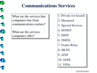
Communications Services
Communications Services. Connection Oriented Service A connection is established Data is sent or received over this connection Connection may be terminated when session is complete or may be permanent This paradigm is similar to telephone service Connectionless-Oriented Service

Communications Services
E N D
Presentation Transcript
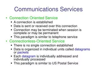
Communications Services • Connection Oriented Service • A connection is established • Data is sent or received over this connection • Connection may be terminated when session is complete or may be permanent • This paradigm is similar to telephone service • Connectionless-Oriented Service • There is no single connection established • Data is organized in individual units called datagrams or packets • Each datagram is individually addressed and individually processed • This paradigm is similar to US Postal Service
The Internet • The Internet protocols provide applications with both a connection and connectionless services • The network layer, the data delivery service, provides only a connectionless service • The basic unit of data processed by the network layer is the IP Datagram • Each datagram is individually addressed and individually processed • There is no guarantee that the datagrams that comprise a ‘session’ will follow the same path or that they will arrive in order
Header Data Destination IP Address Source IP Address IP Datagram • IP datagram is variable length (up to 64K bytes) • Data length can be as little as 1 byte • Source and IP addresses in the datagram used route the datagram to its destination
Configuration for routing example /27 /27 /8 /24 /24
Routing Table for R1 MaskDest. Next HopI. 255.0.0.0 111.0.0.0 -- m0 255.255.255.224 193.14.5.160 - m2 255.255.255.224 193.14.5.192 - m1 -------------------------------------------------------------------------------------255.255.255.255 194.17.21.16 111.20.18.14 m0 ------------------------------------------------------------------------------------- 255.255.255.0 192.16.7.0 111.15.17.32 m0 255.255.255.0 194.17.21.0 111.20.18.14 m0 ------------------------------------------------------------------------------------- 0.0.0.0 0.0.0.0 111.30.31.18 m0
Example 1 Router R1 receives a datagram for destination 192.16.7.14; the algorithm applies the masks row by row to the destination address until a match (with the value in the second column) is found:
Direct delivery 192.16.7.14 & 255.0.0.0 192.0.0.0 no match 192.16.7.14 & 255.255.255.224 192.16.7.0 no match 192.16.7.14 & 255.255.255.224 192.16.7. no match Host-specific 192.16.7.14 & 255.255.255.255192.16.7.14 no match Network-specific 192.16.7.14 & 255.255.255.0 192.16.7.0 match
Example 2 Router R1 receives a datagram for destination 193.14.5.176; the algorithm applies the masks row by row to the destination address until a match is found: Direct delivery 193.14.5.176 & 255.0.0.0 193.0.0.0 no match 193.14.5.176 & 255.255.255.224 193.14.5.160 match
Example 3 Router R1 receives a datagram for destination 200.34.12.34; the algorithm applies the masks row by row to the destination address until a match is found:
Direct delivery 200.34.12.34 & 255.0.0.0 200.0.0.0 no match 200.34.12.34 & 255.255.255.224 200.34.12.32 no match 200.34.12.34 & 255.255.255.224 200.34.12.32 no match Host-specific 200.34.12.34 & 255.255.255.255 200.34.12.34 no match Network-specific 200.34.12.34 & 255.255.255.0 200.34.12.0 no match 200.34.12.34 & 255.255.255.0 200.34.12.0 no match Default 200.34.12.34 & 0.0.0.0 0.0.0.0. match
IP Datagram Service • Best-Effort delivery • Datagrams could be lost • Datagram delivery may be delayed • Datagrams may arrive out of order • Datagrams could arrive corrupted • Datagrams might even be duplicated • Upper layers must cope with these conditions
IP Datagram VERS Version number, now version 4 Version 6 slowly being deployed HLEN Length of IP header in 32 –bit words Service Type Intended as a service category Minimize delay Minimize cost Maximize throughput Maximize reliability Total Length Total length of datagram Header + data
IP Datagram Identification Used to break up large datagrams Flags Fragment Offset Discussed later Time to Live Count, decremented at each hop When zero, datagram discarded
IP Datagram Protocol Specifies which upper layer protocol created datagram TCP(6), UDP(17), ICMP(1) Header Checksum Checksum applied to header only 1-s complement sum of 16 bit words of header Source IP address Destination IP address
Network Byte Order • Different processors store binary values differently • Some store integers with most significant bits in low memory address positions Big Endian • Others may store in reverse order Little Endian • Standard for IP is Big Endian • Systems provide convenient conversion routines
Header Data Type = 0800 CRC Ethernet Source Address Ethernet Destination Address Encapsulation • An IP datagram inserted inside a frame at layer 2, such as Ethernet
Demultiplexing • A frame arrives at a host, say Ethernet • Destination hardware address is compared • Type field is checked • 0806 ARP frame • 0835 RARP frame • 0800 IP datagram • If IP datagram, protocol field is checked • 1 ICMP • 6 TCP • 17 UDP
Maximum Transmission Unit(MTU) • Most data link layers enforce a maximum frame size • Maximum payload for Ethernet frames is 1500 bytes • Other data link layers may impose even shorter frame lengths • A datagram may travel over a path that includes different data link layers • The smallest MTU in the path is called the path MTU
Fragmentation • IP datagrams can be as much as 65,536 bytes • This cannot fit into most data link layer frames, including Ethernet • The IP datagram must be broken down into appropriate size fragments • The fragments will need to be reassembled at a later point • Three fields in the IP datagram header control fragmentation
D M IP Header Identification - a counter incremented by 1 for each datagram FlagsD = do not fragment M = More fragments Fragmentation Offset - relative position of fragment in original datagram (divided by 8)
Detailed example
Fragmentation • The header of the original datagram is copied into each fragment with affected fields modified • After fragmentation each fragment is treated as a separate datagram • Reassembly of original datagram is done at final destination • There is no guarantee that every fragment will reach its destination • At destination, a reassembly timer is set • Either all fragments arrive in that time or all other fragments discarded