Download
1 / 18
180 likes | 393 Vues
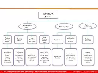
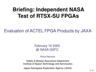
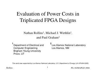
2005 MAPLD International Conference. Evaluation of Actel FPGA Products by JAXA. Yasuo SAKAIDE 1 , Norio NEMOTO 2 Kimiharu Kariu 1 , Masahiko Midorikawa 1 , Yoshiya Iide 1 , Masakazu Ichikawa 1 , Tamotsu Yokose 1 , Yoshihisa Tsuchiya 1 , Toshifumi Arimitsu 1 ,

E N D
2005 MAPLD International Conference Evaluation of Actel FPGA Products by JAXA Yasuo SAKAIDE1, Norio NEMOTO2 Kimiharu Kariu1, Masahiko Midorikawa1, Yoshiya Iide1, Masakazu Ichikawa1, Tamotsu Yokose1, Yoshihisa Tsuchiya1, Toshifumi Arimitsu1, Noriko Yamada2, Hiroyuki Shindou2, Satoshi Kuboyama2, Sumio Matsuda2, and Takashi Tamura2 High-Reliability Components Corporation (HIREC)1 Japan Aerospace Exploration Agency (JAXA)2 1
Background Failures on programmed anti-fuse of Actel FPGA products which were built in the 0.25 um MEC/Tonami process have been reported in U.S. since 2003. While the investigation and evaluation have been performed by NASA, Industry Tiger Team (ITT) and so forth, the root cause of failure is not clarified and a lot of users are really concerned about the application of Actel FPGAs (MEC) for flight units under the present condition. Japan Aerospace Exploration Agency (JAXA) started to evaluate Actel FPGA products; A54SX-A (MEC) and RTSX-SU (UMC) in the end of 2004. 2
Test Objectives (1) MEC die devices - To determine the acceleration factors of the antifuse failures by performing long-term life tests at various temperatures. (2) UMC die devices - To evaluate the reliability for space applications by performing long-term life tests and radiation tests. 3
Test Vehicle (1) Evaluation test circuit – Diagram Design features 1- 4-input AND-OR chains: Maximum utilization of antifuses 2- Stable operation using an external clock circuit: Easier failure detection 3- R-cells driven by skewed clock: Delays detectable to less than 10nsec 4- Continuous monitoring of XORed outputs from the same circuit block: Real-time detection of failures x4:32A/32SU x8:72A 6
Test Vehicle (2) The number of antifuses in test vehicles 7
Test Environment Handling Environment ESD protected / designated area - ESD safe table mats - Ionizer (ATE area) - Antistatic floor etc. - Vacuum wands - Globes required - Wrist strap - ESD shoes Test Systems Prevention of EOS - Signals and power supplies within recommended operating conditions described in datasheet (ex. Power strip with noise filter) 8
Initial t distribution PLH 140 140 R7 R6 120 120 R5 100 100 R4 R3 80 80 R2 R1 Frequency of Occurrence 60 60 R0 40 40 20 20 0 0 135 145 150 >155 140 t [ns] PLH unstable Test Results (2): Initial tPLH Distribution Initial tPLH distribution – A54SX-A (MEC, old programming algorithm) A54SX32A A54SX72A tPLH anomalies were observed on initial electrical parameter test for A54SX-A (MEC die) FPGAs 9
Test Results (3): Weibull Plots • Weibull plots for 72A samples were successfully obtained and the failure mode was infant mortality. • Weibull plots for 32A samples were slightly different and and statistically poor because of small sample size. 10
Test Results (4):Failure Rate as a Function of Time Failure rates were calculated based on the Weibull plots for 72A samples. The failure rates are consistent with 32A and 72A data within practical application purpose.It was considered that the difference of the failure rate was caused by lot difference because of the same structure of 32A and 72A. 11
Test Results (5):Acceleration Factor Ea=0.002eV Temperature acceleration factor was calculated based on the Weibull plots for 72A samples Given activation energy was too small to screen out the defective antifuses throughout PPBI (125 deg.C, 240 hours) . 12
Programming ATE test Loading to test board Waveform check at R.T. Rise of Temperature Waveform check at Specified temperature Start of life test Discussion(1):Failures before life tests # of failure example: 2/100 18/98 2/79 1st 2nd There are several number of operations before start of the life test where defective antifuses can be failed. It was confirmed that the failures detected in the operations should be included in Weibull plots. 19/77 - These failures should be included in Weibull Plot 13
Discussion (2): Antifuse Delay Time Trend SX72A,70deg.C,1MHz,1000H SX72A,25deg.C,1MHz,1000H SX72A,125deg.C,1MHz,1000H There were several features of the delay time trend observed with defective antifuses. In most cases, the delay time once increased and then did not drastically changed. It was observed that the delay time first increased and then returned close to initial value. 14
Discussion(3):Antifuse Delay Time Distribution The delay time increase observed with failed antifuses has log-normal distribution. The fact may suggest certain physical mechanism. 15
Discussion(4): Survival Probability Survival probability until mission duration was evaluated using Weibull fitting parameter. This evaluation was included effects of PPBI, 240hours and 125deg. C, and acceleration factor of temperature (operating temp. is 40deg.C) 16
Discussion(5): Policy of JAXA Almost installed FPGA in JAXA satellites and rockets was performed post programmed burn-in (PPBI) . But temperature acceleration factor of this failure mode was too small to screen out the defects by PPBI. On the other hand, any defects were not observed in the evaluation test of UMC die FPGAs in JAXA. Based on these results, it was suggested that MEC die FPGAs shall be replaced UMC ones in almost JAXA projects. 17
Conclusions • Weibull plots for the antifuse failures of A54SX-A (MEC) FPGAs were successfully obtained. The failure mode was infant mortality. • Given temperature acceleration factor was too small to screen out the defective antifuses throughout PPBI (125deg.C 240hours) • No defective antifuses were observed for RTSX-SU (UMC) FPGAs. • Based on the results, the MEC die FPGAs shall be replaced with UMC ones by decision of JAXA projects. • There was a new finding, i.e. the increased delay time distribution for failed antifuses. • Temperature cycling tests are being performed. No defective antifuses were observed at 800 cycles for MEC die FPGAs. • The radiation tests are also being performed for UMC die FPGAs. 18