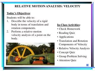
Today’s Objectives : Students will be able to:
140 likes | 373 Vues
RELATIVE MOTION ANALYSIS: VELOCITY. Today’s Objectives : Students will be able to: Describe the velocity of a rigid body in terms of translation and rotation components. Perform a relative-motion velocity analysis of a point on the body. In-Class Activities : • Check Homework

Today’s Objectives : Students will be able to:
E N D
Presentation Transcript
RELATIVE MOTION ANALYSIS: VELOCITY • Today’s Objectives: • Students will be able to: • Describe the velocity of a rigid body in terms of translation and rotation components. • Perform a relative-motion velocity analysis of a point on the body. In-Class Activities: • Check Homework • Reading Quiz • Applications • Translation and Rotation Components of Velocity • Relative Velocity Analysis • Concept Quiz • Group Problem Solving • Attention Quiz
APPLICATIONS As the slider block A moves horizontally to the left with vA, it causes the link CB to rotate counterclockwise. Thus vB is directed tangent to its circular path. Which link is undergoing general plane motion? Link AB or link BC? How can the angular velocity, of link AB be found?
APPLICATIONS (continued) Planetary gear systems are used in many automobile automatic transmissions. By locking or releasing different gears, this system can operate the car at different speeds. How can we relate the angular velocities of the various gears in the system?
Disp. due to translation drB = drA + drB/A Disp. due to rotation Disp. due to translation and rotation RELATIVE MOTION ANALYSIS (Section 16.5) When a body is subjected to general plane motion, it undergoes a combination of translation and rotation. Point A is called the base point in this analysis. It generally has a known motion. The x’- y’ frame translates with the body, but does not rotate. The displacement of point B can be written:
RELATIVE MOTION ANALYSIS: VELOCITY The velocity at B is given as :(drB/dt) = (drA/dt) + (drB/A/dt)or vB = vA + vB/A Since the body is taken as rotating about A, vB/A = drB/A/dt = w × rB/A Here w will only have a k component since the axis of rotation is perpendicular to the plane of translation.
RELATIVE MOTION ANALYSIS: VELOCITY (continued) vB = vA + w × rB/A When using the relative velocity equation, points A and B should generally be points on the body with a known motion. Often these points are pin connections in linkages. For example, point A on link AB must move along a horizontal path, whereas point B moves on a circular path. The directions of vA and vB are known since they are always tangent to their paths of motion.
RELATIVE MOTION ANALYSIS: VELOCITY (continued) vB = vA + w × rB/A When a wheel rolls without slipping, point A is often selected to be at the point of contact with the ground. Since there is no slipping, point A has zero velocity. Furthermore, point B at the center of the wheel moves along a horizontal path. Thus, vB has a known direction, e.g., parallel to the surface.
PROCEDURE FOR ANALYSIS The relative velocity equation can be applied using either a Cartesian vector analysis or by writing scalar x and y component equations directly. Scalar Analysis: 1. Establish the fixed x-y coordinate directions and draw a kinematic diagram for the body. Then establish the magnitude and direction of the relative velocity vector vB/A. 2. Write the equation vB = vA + vB/A. In the kinematic diagram, represent the vectors graphically by showing their magnitudes and directions underneath each term. 3. Write the scalar equations from the x and y components of these graphical representations of the vectors. Solve for the unknowns.
PROCEDURE FOR ANALYSIS (continued) Vector Analysis: 1. Establish the fixed x - y coordinate directions and draw the kinematic diagram of the body, showing the vectors vA, vB, rB/A and w. If the magnitudes are unknown, the sense of direction may be assumed. 2. Express the vectors in Cartesian vector form (CVN) and substitute them into vB = vA + w × rB/A. Evaluate the cross product and equate respective i and j components to obtain two scalar equations. 3. If the solution yields a negative answer, the sense of direction of the vector is opposite to that assumed.
EXAMPLE I Given: Roller A is moving to the right at 3 m/s. Find: The velocity of B at the instant = 30. Plan: 1. Establish the fixed x - y directions and draw a kinematic diagram of the bar and rollers. 2. Express each of the velocity vectors for A and B in terms of their i, j, k components and solve vB = vA + w × rB/A.
EXAMPLE I (continued) Solution: Kinematic diagram: y Express the velocity vectors in CVN vB = vA + w × rB/A -vB j= 3 i + [ wk × (-1.5cos30i +1.5sin 30j )] -vB j= 3 i – 1.299 wj – 0.75 wi y Equating the i and j components gives: 0 = 3 – 0.75 w -vB = – 1.299 w Solving: w = 4 rad/s or w= 4 rad/s k vB = 5.2 m/s or vB = -5.2 m/s j
EXAMPLE II Given: Crank rotates OA with an angular velocity of 12 rad/s. Find:The velocity of piston B and the angular velocity of rod AB. Plan: Notice that point A moves on a circular path. The directions of vA is tangent to its path of motion. Draw a kinematic diagram of rod AB and use vB = vA + wAB × rB/A.
EXAMPLE II (continued) Solution: Kinematic diagram of AB: Since crack OA rotates with an angular velocity of 12 rad/s, the velocity at A will be: vA = -0.3(12) i = -3.6 i m/s Rod AB. Write the relative-velocity equation: vB = vA + wAB × rB/A vB j= -3.6 i + wAB k × (0.6cos30 i − 0.6sin30 j ) vB j = -3.6 i + 0.5196 wAB j + 0.3 wAB i By comparing the i, j components: i: 0 = -3.6 + 0.3 wABwAB = 12 rad/s j: vB = 0.5196wAB vB = 6.24 m/s
GROUP PROBLEM SOLVING Given:The ring gear R is rotating at wR = 3 rad/s, and the sun gear S is held fixed, wS = 0. Find: The angular velocity of the each of the planet gears P and of shaft A. Plan: Draw the kinematic diagram of gears. Then, apply the relative velocity equations to the gears and solve for unknowns.