Download
1 / 28
280 likes | 551 Vues
DESIGN SUMMARY AND T-H R&D NEEDS OF THE GT-MHR. Workshop on R&D in the Areas of Thermal Fluids and Reactor Safety C. B. Baxi General Atomics, San Diego, CA. Module Below Grade Provides Security and Sabotage Protection. Electrical output 286 MW(e) per module

E N D
DESIGN SUMMARY AND T-H R&D NEEDS OF THE GT-MHR Workshop on R&D in the Areas of Thermal Fluids and Reactor Safety C. B. Baxi General Atomics, San Diego, CA
Module Below Grade Provides Security and Sabotage Protection • Electrical output 286 MW(e) per module • Each module includes Reactor System and Power Conversion System • Reactor System 600 MW(t), 102 column, annular core, hexagonal prismatic blocks, very similar to successful FSV tests • Power Conversion System includes generator, turbine, compressors on single shaft, surrounded by recuperator, pre-cooler and inter-cooler • Natural sabotage protection Grade level 35 M Reactor building
GT-MHR MODLE MELTDOWN-PROOF ADVANCED REACTOR&HIGH EFFICENCYGAS TURBINEPOWER CONVERSIONSYSTEMPOWER LEVEL600 MWt
GT-MHR / LWR COMPARISON ItemGT-MHRLWR Moderator Graphite Water Coolant Helium Water Avg core coolant exit temperature 850° - 1000 °C 310°C Structural material Graphite Steel Fuel clad Graphite & silicon Zircaloy Fuel UCO or PuCO UO2 Fuel damage temperature >2000°C 1260°C Power density, w/cc 6.5 58 - 105 Linear heat rate, kW/ft 1.6 19 Avg thermal neutron energy, eV0.22 0.17 Migration length, cms 57 6 TEST TEST
GT-MHR EMPLOYS DIRECT BRAYTON CYCLE FOR ELECTRICITY GENERATION
PCU PARAMETERS Reactor Power (MWt) 600 Inlet Pressure to turbine (Mpa) 7 Inlet temperature to turbine ( C ) 850 RPM 4400 He Flow (kg/s) 320 TC mass (T) 33 Gen mass 35 Max Load on TC Radial EMB (kN) 28 Max Load on gen Radial EMB 34 Max Load on TS axial EMB 326 Max Load on gen axial EMB 350 Turbine Stages 9 HP Compressor Stages 13 LP Compressor Stages 10
REACTOR SYSTEM Reactor System Design
REPLACEABLE CENTRAL & SIDE REFLECTORS 36 X OPERATING CONTROL RODS BORATED PINS (TYP) CORE BARREL REFUELING PENETRATIONS ACTIVE CORE 102 COLUMNS 10 BLOCKS HIGH 12 X START-UP CONTROL RODS PERMANENT SIDE REFLECTOR 18 X RESERVE SHUTDOWN CHANNELS GT-MHR CORE LAYOUT
FUEL ASSEMBLY IS BASIC STRUCTURAL UNIT OF CORE • Fuel Particle SiC and PyC coatings retain fission products • Fuel compact contains particles • Graphite block supports fuel compacts in arrangement compatible with nuclear reaction and heat transfer to helium • Dowels align coolant holes between blocks 0.8 m x 0.36 m
CORE T/H REQUIREMENTS RequirementLimitBasis Fuel 1250°C (steady state) Fuel Integrity 1600°C (accident) Control rods >2000°C Stress (structural integrity) Graphite blocks Limit T/X, temp, Stress (structural integrity) fluence Core array Limit P (~70 kPa) Flow-induced Vibrations Hot duct 900°C -1000°C Stress(structural integrity)
CORE FLOW DISTRIBUTION • Maximize flow in coolant channels (limit Tfuel) • Adequate control rod flow • Minimize gap flows (1 mm gap needed for refueling) • Uniform coolant channel flows (limit T/X) • Minimize crossflows between coolant channels and gaps • minimize crossflow between control rod channels and gaps
CORE T/H CHARACTERISTICS • Core coolant temperature rise is large • Temperature rise from coolant to fuel is small Control of the coolant temperature rise is very important to reactor core performance • This is opposite from LWR cores, where Tcool is small but Tfuel is large
MHTGR SAFETY RELIES ON THREEBASIC FUNCTIONS RetainRadionuclides inCoated Particles Remove Core Heat Control Heat Generation Control Chemical Attack
APPROACH:PASSIVE SAFETY BY DESIGN • Fission Products Retained in Coated Particles • High temperature stability materials • Refractory coated fuel • Graphite moderator • Worst case fuel temperature limited by design features • Low power density • Low thermal rating per module • Annular core • Passive heat removal • ... CORE CAN’T MELT • Core Shuts Down Without Rod Motion • Large negative temperature coefficient • Coolant Not a Safety Problem • Neutronically and chemically inert: no energy reactions • Single phase • Low stored energy • Operator Not in the Safety Equation • Insensitive to operator error (commission or omission) • Long response times for recovery
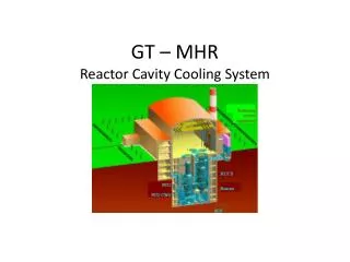
DECAY HEAT REMOVAL PATHS WHEN NORMAL POWER CONVERSION SYSTEM IS UNAVAILABLE Relief Valve Air Blast Heat Exchanger Surge Tank Natural Draft, Air Cooled Passive System Reactor Cavity Cooling System Panels Shutdown Cooling System Heat Exchanger and Circulator • A) Active Shutdown • Cooling System • B) Passive Reactor Cavity • Cooling System • C) Passive Radiation • and Conduction of Afterheat to Silo Containment • (Beyond Design • Basis Event) • . . . DEFENSE-IN-DEPTH BUTTRESSED BY • INHERENT CHARACTERISTICS
HEAT REMOVAL BY PASSIVE MEANS DURING PRESSURIZED CONDUCTION COOLDOWN Heat removed by: • Core Convection • Core Conduction • Core Internal Radiation • Vessel Radiation • RCCS Convection
HEAT REMOVAL BY PASSIVE MEANS DURING DEPRESSURIZED CONDUCTION COOLDOWN Heat removed by: • Core Conduction • Core Internal Radiation • Vessel Radiation • RCCS Convection
GT-MHR FUEL TEMPERATURES REMAIN BELOW DESIGN LIMITS DURING CONDUCTION COOLDOWN EVENTS . . . passive design features ensure fuel remains below 1600°C
TOTAL CORE FLOW RATE DURING CONDUCTION COOLDOWN AT VARIOUS HELIUM INVENTORIES
NEW TEST T-H TEST RESULTS REQUIRED STEADTY STATE • A NUMBER OF TESTS HAVE BEEN PERFORMED ACCIDENT CONDITIONS • DATA REQUIRED ON CONDUCTION COOLING
CONCLUSIONS • Coupling Modular Helium Reactor with Gas Turbine (turbomachine, magnetic bearings, recuperator) results in unique passively safe reactor • GT-MHR has safety characteristics similar to MHTGR • Similar conduction cooldown transient results • Similar reactivity event transient results • Reduced frequency of water ingress events • GT-MHR maintains high level of safety eliminating core melt without operator action
SUMMARY OF R&D REQUIRED • Validate engineering assumptions • Assess mixing and flow distribution • Assess gap and cross flows • Assess natural circulation
GT-MHR T-H R&D TOPICS STEADY STATE • Lower plenum mixing during normal operation • Turbine outlet mixing during loss of load or rapid load change • Flow distribution from cold duct to upper plenum • Core gap flow and cross flow ACCIDENT • Natural circulation in reactor cavity • Natural circulation in RCCS • Natural circulation within reactor vessel • SCS startup and transition from natural circulation to forced convection cooling • Air ingress