Appearance-Based Equivalence Checking of Circuits: Transforming Revised Circuits
This document presents a methodology for appearance-based equivalence checking between a golden circuit and a revised circuit. The process involves transforming the revised circuit to resemble the golden circuit by converting multiple output circuits into single output circuits. Each pair is then examined for equivalence through structural comparison. Steps include transforming circuits into AIG form, identifying redundant elements, and determining the need for rectified additions or removals. Future work will focus on addressing faults such as missing or extra NOT gates.

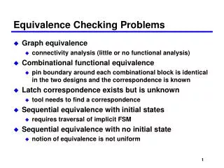
Appearance-Based Equivalence Checking of Circuits: Transforming Revised Circuits
E N D
Presentation Transcript
Appearance-Based Equivalence Checking Speaker: Daw-Ming Lee Advisor: Chun-Yao Wang 2009.06.12
Introduction • Given two circuits, golden circuit and revised circuit • According to their appearance , transform revised circuit to make it similar to golden circuit
Step I • Convert multiple outputs circuit to many single output circuits, and examine each pair of single output circuits are equivalent or not • Transform each single output circuit to AIG form
Transformation flow chart Compare the golden and revised circuits Structurally identical? T End F Choose one target wire to remove/add Redundant? F Add rectified circuit T Remove/add the target wire
RAR a a b b c a c a a b b c a c
RAR a a b b c a c 1 a 0 b c 1/0 1 a c 1 0 violate MA Redundant addition, no need to add rectified circuit
RAR a b a c b c a c 1 a 0 b 1 c 1 a 1 c 1 1/0
IRRA a a b b a b a a b b a a b b
IRRA a a b b a a b b a b 0 0/1 a b 1/0 1/0 a 0 b
IRRA a a b b a a b b a b 1 a a 0/1 b 1 Redundant remove, no need to add rectified circuit
IRRA a a b b a a b b a b a b
Future work • Find the rectified circuit of the missing/extra NOT fault • IRAA a a b b a a b b