Episcopal High School Science Facility Renovation Project Overview
350 likes | 376 Vues
This presentation outline introduces the renovation project of the Episcopal High School science facility, including the background, wall system analysis, mechanical assessment, stormwater reclamation system study, conclusions, and recommendations. The project, managed by Jack E. Nill III, covers key features such as LEED Silver Rating, unique stormwater management system, and various laboratory types within the facility. The construction project details, costs, team involved, and design aspects are highlighted, emphasizing the sustainability goals and energy efficiency measures incorporated. The analysis includes a focus on the wall system redesign, air infiltration causes, benefits of an air barrier, and design criteria for improving the building envelope performance.

Episcopal High School Science Facility Renovation Project Overview
E N D
Presentation Transcript
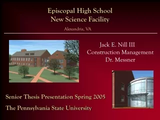
Presentation Outline Introduction Project Background Wall System Analysis and Redesign Mechanical Analysis Storm Water Reclamation System Analysis Conclusions & Recommendations Questions Jack E. Nill III Construction Management
Introduction Intended Use: As a laboratory and science teaching facility for Episcopal High School Introduction Project Background Wall System Analysis Mechanical Analysis SWR Systems Analysis Conclusions Key Issues/Features: • LEED Silver Rating • Laboratory Fume Hoods require 100% outside air • Unique Storm Water Management system • Architectural Rotunda to geographically tie to Jefferson Memorial • Four different types of Laboratories with in the facility Jack E. Nill III Construction Management
Project Background Project Cost: $9.1 Million Project Size: 43,000 SF, 2 Stories Architecture: Red Brick Façade with Aluminum Paneling Architectural Rotunda with Aluminum framed glazing Greenhouse on south end Project Start : August 2004 Project Finish: May 2005 Introduction Project Background Wall System Analysis Mechanical Analysis SWR Systems Analysis Conclusions Jack E. Nill III Construction Management
Project Background Project Team Owner/Occupant: Episcopal High School Design Architect: Graham Gund Architects Structural Engineer: LeMessurier Consultants MEP Engineer: R.G. Vanderweil Project Management General Contractor: Forrester Construction CM: Advanced Project Management Introduction Project Background Wall System Analysis Mechanical Analysis SWR Systems Analysis Conclusions Jack E. Nill III Construction Management
Project Background Relevant Systems Background Building Envelope: • Red Brick Veneer • Metal Stud Back-up • ½” Sheathing • Typical Building Paper with continuous vapor barrier • Batt insulation • Gypsum Wall Board Mechanical System: • Air cooled Rotary Chiller (194 Tons), • Split-System Air-Conditioning Unit System w/ VAV and CV boxes • Three Air Handling Units totaling 37450 cfm capacity Introduction Project Background Wall System Analysis Mechanical Analysis SWR Systems Analysis Conclusions Jack E. Nill III Construction Management
Project Background Introduction Project Background Wall System Analysis Mechanical Analysis SWR Systems Analysis Conclusions Jack E. Nill III Construction Management
LEED Summary LEED-NC Silver Rating (33-38 point) • EHS New Science Facility scheduled to obtain 33 points Focus Areas: • EA – Energy and Atmosphere (3 of 17 possible points and all Prerequisites met) • WE – Water Efficiency (5 of 5 possible points and all Prerequisites met) • ID - Innovation and Design Process (3 of 5 possible points) Introduction Project Background Wall System Analysis Mechanical Analysis SWR Systems Analysis Conclusions Jack E. Nill III Construction Management
Analysis I: Wall System Analysis and Redesign Background: • Up to 40% of energy consumed to heat or cool a building is due to Air infiltration. Goals: • Implement a Zero Percent Air Infiltration System in order to lower the infiltration values of the wall system significantly, analyze the impacts of the new system, and determine the feasibility of the new system in green construction practices. Introduction Project Background Wall System Analysis Mechanical Analysis SWR Systems Analysis Conclusions Jack E. Nill III Construction Management
Analysis I: Wall System Analysis andRedesign Causes of Infiltration • The Stack Effect • Chimney’s • Wind • Forced Hot-Air Heating Systems Introduction Project Background Wall System Analysis Mechanical Analysis SWR Systems Analysis Conclusions Jack E. Nill III Construction Management
Advantages of Using an Air Barrier • Prevent premature deterioration of the building envelope • Enhance thermal performance of the structure and save energy costs • Improve comfort for the building occupants • Decreased moisture infiltration into wall cavity, lowering probability of mold issues within the building envelope Introduction Project Background Wall System Analysis Mechanical Analysis SWR Systems Analysis Conclusions Jack E. Nill III Construction Management
Analysis I: Wall System Analysis and Redesign Design Criteria • Air Barrier Product: Grace Perm-A-Barrier membrane in place of Building Paper and Continuous Vapor Barrier • Grace Perm-A-Barrier Wall conditioner applied prior to self adhesive membrane • Membrane wrapped into window frames and sealed by glazer • Bituthene mastic used to seal all penetrations • Perm-A-Barrier Wall Flashing used and sealed to membrane Introduction Project Background Wall System Analysis Mechanical Analysis SWR Systems Analysis Conclusions Jack E. Nill III Construction Management
Introduction Project Background Wall System Analysis Mechanical Analysis SWR Systems Analysis Conclusions Perm-A-Barrier Membrane Bituthene Mastic PAB Wall Flashing Jack E. Nill III Construction Management
CM Concerns and Issues • Quality of Construction!!! • Coordination with other trades for the building envelope • Integration with the Roof and Foundation wall • Availability of Materials • Cost • Schedule impacts Introduction Project Background Wall System Analysis Mechanical Analysis SWR Systems Analysis Conclusions Jack E. Nill III Construction Management
Cost and Schedule Impacts of Perm-A-Barrier Introduction Project Background Wall System Analysis Mechanical Analysis SWR Systems Analysis Conclusions Initially $33,558 more expensive ($1.41/SF more) Adds 7 days to the schedule but not on the critical path Jack E. Nill III Construction Management
Infiltration Impacts Introduction Project Background Wall System Analysis Mechanical Analysis SWR Systems Analysis Conclusions Jack E. Nill III Construction Management
Conclusions and Recommendations EHS New Science Facility • For this particular project an Air Barrier Wall System is not a feasible solution to a more efficient building envelope. Industry • In more extreme climates such as Canada, however, this type of system has proven to significantly reduce energy costs associated with heating the building. • Annual cost savings of up to $6,000 have been seen by using similar Air Barrier systems to reduce air leakage. • Could prove useful on other high performance/green projects in the future. Introduction Project Background Wall System Analysis Mechanical Analysis SWR Systems Analysis Conclusions Jack E. Nill III Construction Management
Analysis II: Mechanical Analysis Background: • Fume Hoods in the laboratories and the recent adoption of the 2000 International Energy Conservation Code (ICC) by the state of VA were driving factors in this analysis • High performance Mechanical Systems can result in long term energy savings as well as cost savings to the owner Introduction Project Background Wall System Analysis Mechanical Analysis SWR Systems Analysis Conclusions Goals: • To maximize energy efficiency of the mechanical system by adding sustainable upgrades • Determine the feasibility of such upgrades using DOE 2.2 cost modeling and based on ROI to the owner and CM issues encountered Jack E. Nill III Construction Management
Sustainable Upgrades • Variable air volume with variable frequency drives • Heat Recovery on AHU 3 • Water Cooled Chiller vs. Air Cooled Chiller • CO2monitors Introduction Project Background Wall System Analysis Mechanical Analysis SWR Systems Analysis Conclusions Jack E. Nill III Construction Management
DOE 2.2 Energy Cost Modeling What is DOE 2.2? - Energy cost modeling software used in the industry to determine the energy costs of a building based on its components and location (Department Of Energy) Assumptions: 1) Electric Costs based on Virginia Electric and Power Company Schedules GS-3 with fuel charges of $0.01613/kWh 2) Gas costs based on Washington Gas 3) Two position hood control in both cases 4) Chiller performance based on performance info provided from Trane 5) Weather data averaged over 25 year records Introduction Project Background Wall System Analysis Mechanical Analysis SWR Systems Analysis Conclusions Jack E. Nill III Construction Management
DOE 2.2 Energy Cost Modeling Introduction Project Background Wall System Analysis Mechanical Analysis SWR Systems Analysis Conclusions Net Cost Savings of $.77/SF/Year A16% Energy Savings seen (1 LEED Point) Jack E. Nill III Construction Management
DOE 2.2 Energy Cost Modeling Introduction Project Background Wall System Analysis Mechanical Analysis SWR Systems Analysis Conclusions Jack E. Nill III Construction Management
CM Concerns Introduction Project Background Wall System Analysis Mechanical Analysis SWR Systems Analysis Conclusions Jack E. Nill III Construction Management
Conclusions & Recommendations • The Sustainable Upgrades result in a $19,900/year savings which will pay for itself in <5 years • Cost Savings to the owner will be seen after 5 years of operation • Early Coordination and quality of construction is the key to mitigating CM concerns Introduction Project Background Wall System Analysis Mechanical Analysis SWR Systems Analysis Conclusions Jack E. Nill III Construction Management
Analysis III: Storm Water Reclamation System Background: • In the United States approximately 340 billion gallons of water are withdrawn from the sources available per day. • SWR Systems can reduce potable water usage on a project by up to 60% just by reusing rain water • A recent survey indicated that 69% of industry members have not worked on a project with a SWR system. Introduction Project Background Wall System Analysis Mechanical Analysis SWR Systems Analysis Conclusions Goals: • To study Existing SWR systems and their issues impacting construction to better understand how to utilize such systems without incurring cost negating the benefits gained. Jack E. Nill III Construction Management
Analysis III: Storm Water Reclamation System What is a SWR system? • A system that catches rain water runoff and stores it in a storage tank to be treated and reused in the building or irrigation system to reduce the amount of potable water required from the source Introduction Project Background Wall System Analysis Mechanical Analysis SWR Systems Analysis Conclusions Case Studies • EHS New Science Facility • Chesapeake Bay Foundation Philip Merill Environmental Center • The PSU SALA Building Jack E. Nill III Construction Management
EHS New Science Facility SWR Schematic Introduction Project Background Wall System Analysis Mechanical Analysis SWR Systems Analysis Conclusions Jack E. Nill III Construction Management
Introduction Project Background Wall System Analysis Mechanical Analysis SWR Systems Analysis Conclusions Jack E. Nill III Construction Management
Introduction Project Background Wall System Analysis Mechanical Analysis SWR Systems Analysis Conclusions Jack E. Nill III Construction Management
Analysis III: Storm Water Reclamation Systems EHS New Science Facility Introduction Project Background Wall System Analysis Mechanical Analysis SWR Systems Analysis Conclusions Jack E. Nill III Construction Management
Analysis III: Storm Water Reclamation Systems Chesapeake Bay Foundation Philip Merill Center Introduction Project Background Wall System Analysis Mechanical Analysis SWR Systems Analysis Conclusions Jack E. Nill III Construction Management
Analysis III: Storm Water Reclamation Systems PSU SALA Building Introduction Project Background Wall System Analysis Mechanical Analysis SWR Systems Analysis Conclusions Jack E. Nill III Construction Management
Conclusions & Recommendations • The Air Barrier Wall system does not work well for this project but may be explored for future uses with high performance/green buildings • The upgraded mechanical system is an excellent way to cut energy usage and save energy costs in the long run • The SWR systems are an extremely useful tool to reduce the use of potable water and protect out natural resources. They are still extremely new but with proper planning and coordination they can be implemented with minimal conflicts on projects. Introduction Project Background Wall System Analysis Mechanical Analysis SWR Systems Analysis Conclusions Jack E. Nill III Construction Management
Acknowledgements Thank you to: • Penn State AE Faculty and Advisors • Forrester Construction Company • Graham Gund Architects • R.G. Vanderweil Engineers (Mechanical Engineer) • My Friends and Family Introduction Project Background Wall System Analysis Mechanical Analysis SWR Systems Analysis Conclusions Jack E. Nill III Construction Management
Introduction Project Background Wall System Analysis Mechanical Analysis SWR Systems Analysis Conclusions ? Questions ? Jack E. Nill III Construction Management