Download
1 / 25
400 likes | 696 Vues
Introduction to VHDL Multiplexers. Discussion D1.1. Multiplexers. A multiplexer is a digital switch. MUX. 1 output, Z = X(s). 2 n inputs X(0, 2 n -1). n control lines s( 0, n-1). 4 x 1. MUX. s1. s0. Y. 0 0 C0 0 1 C1 1 0 C2 1 1 C3. Multiplexers. C0. C1. Y.

E N D
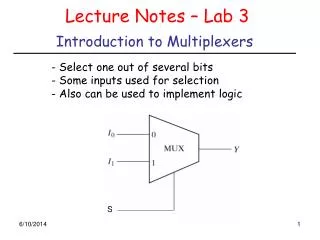
Introduction to VHDLMultiplexers Discussion D1.1
Multiplexers A multiplexer is a digital switch MUX 1 output, Z = X(s) 2n inputs X(0, 2n -1) n control lines s( 0, n-1)
4 x 1 MUX s1 s0 Y 0 0 C0 0 1 C1 1 0 C2 1 1 C3 Multiplexers C0 C1 Y C2 C3 s1 s0
4 x 1 MUX Multiplexers s1 s0 Y C0 0 0 C0 0 1 C1 1 0 C2 1 1 C3 C1 Y C2 C3 s1 s0 A multiplexer is a digital switch 0 0
4 x 1 MUX Multiplexers s1 s0 Y C0 0 0 C0 0 1 C1 1 0 C2 1 1 C3 C1 Y C2 C3 s1 s0 0 1
4 x 1 MUX Multiplexers s1 s0 Y C0 0 0 C0 0 1 C1 1 0 C2 1 1 C3 C1 Y C2 C3 s1 s0 1 0
4 x 1 MUX Multiplexers s1 s0 Y C0 0 0 C0 0 1 C1 1 0 C2 1 1 C3 C1 Y C2 C3 s1 s0 1 1
A 2 x 1 MUX Behavior if (s0 = '0') then Z := A; else Z := B; end if;
if (s0 = '0') then A := C0; B := C2; else A := C1; B := C3; end if; A 4 x 1 MUX if (s1 = '0') then if (s0 = '0') then Z := C0; else Z := C1; end if; else if (s0 = '0') then Z := C2; else Z := C3; end if; end if; if (s1 = '0') then Z := A; else Z := B; end if;
A 4 x 1 MUX case s is when "00" => Z <= C0; when "01" => Z <= C1; when "10" => Z <= C2; when others => Z <= C3; end case;
n-line 2-to-1 Multiplexer n-line 2 x 1 MUX a(n-1:0) y(n-1:0) b(n-1:0) sel y 0 a 1 b sel
a(n-1:0) n-line 2 x 1 y(n-1:0) MUX b(n-1:0) sel An n-line 2 x 1 MUX library IEEE; use IEEE.std_logic_1164.all; entity mux2g is generic (width:positive); port ( a: in STD_LOGIC_VECTOR(width-1 downto 0); b: in STD_LOGIC_VECTOR(width-1 downto 0); sel: in STD_LOGIC; y: out STD_LOGIC_VECTOR(width-1 downto 0) ); end mux2g;
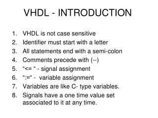
generic statement defines width of bus Entity Each entity must begin with these library and use statements library IEEE; use IEEE.std_logic_1164.all; entity mux2g is generic (width:positive); port ( a: in STD_LOGIC_VECTOR(width-1 downto 0); b: in STD_LOGIC_VECTOR(width-1 downto 0); sel: in STD_LOGIC; y: out STD_LOGIC_VECTOR(width-1 downto 0) ); end mux2g; port statement defines inputs and outputs
Entity Mode: in or out library IEEE; use IEEE.std_logic_1164.all; entity mux2g is generic (width:positive); port ( a: in STD_LOGIC_VECTOR(width-1 downto 0); b: in STD_LOGIC_VECTOR(width-1 downto 0); sel: in STD_LOGIC; y: out STD_LOGIC_VECTOR(width-1 downto 0) ); end mux2g; Data type: STD_LOGIC, STD_LOGIC_VECTOR(width-1 downto 0);
Standard Logic library IEEE; use IEEE.std_logic_1164.all; type std_ulogic is ( ‘U’, -- Uninitialized ‘X’ -- Forcing unknown ‘0’ -- Forcing zero ‘1’ -- Forcing one ‘Z’ -- High impedance ‘W’ -- Weak unknown ‘L’ -- Weak zero ‘H’ -- Weak one ‘-’); -- Don’t care
Standard Logic Type std_ulogic is unresolved. Resolved signals provide a mechanism for handling the problem of multiple output signals connected to one signal. subtype std_logic is resolved std_ulogic;
a(n-1:0) n-line 2 x 1 y(n-1:0) MUX b(n-1:0) sel Architecture architecture mux2g_arch of mux2g is begin mux2_1: process(a, b, sel) begin if sel = '0' then y <= a; else y <= b; endif; end process mux2_1; end mux2g_arch; Note: <= is signal assignment
Architecture entity name process sensitivity list architecture mux2g_arch of mux2g is begin mux2_1: process(a, b, sel) begin if sel = '0' then y <= a; else y <= b; endif; end process mux2_1; end mux2g_arch; Sequential statements (if…then…else) must be in a process Note begin…end in process Note begin…end in architecture
Top-level design for Lab 1 library IEEE; use IEEE.STD_LOGIC_1164.all; use IEEE.std_logic_unsigned.all; entity Lab1 is port( SW : in STD_LOGIC_VECTOR(7 downto 0); BTN0 : in STD_LOGIC; LD : out STD_LOGIC_VECTOR(3 downto 0) ); end Lab1;
architecture Lab1_arch of Lab1 is component mux2g generic( width : POSITIVE); port( a : in std_logic_vector((width-1) downto 0); b : in std_logic_vector((width-1) downto 0); sel : in std_logic; y : out std_logic_vector((width-1) downto 0)); end component; constant bus_width: integer := 4; begin mux2: mux2g generic map(width => bus_width) port map (a => SW(7 downto 4),b => SW(3 downto 0), sel => BTN0, y => LD); end Lab1_arch;
Lab1.ucf #PACE: Start of PACE I/O Pin Assignments NET "BTN0" LOC = "M13" ; NET "LD<0>" LOC = "K12" ; NET "LD<1>" LOC = "P14" ; NET "LD<2>" LOC = "L12" ; NET "LD<3>" LOC = "N14" ; NET "SW<0>" LOC = "F12" ; NET "SW<1>" LOC = "G12" ; NET "SW<2>" LOC = "H14" ; NET "SW<3>" LOC = "H13" ; NET "SW<4>" LOC = "J14" ; NET "SW<5>" LOC = "J13" ; NET "SW<6>" LOC = "K14" ; NET "SW<7>" LOC = "K13" ;
architecture Lab1_arch of Lab1 is component mux2g generic( width : POSITIVE); port( a : in std_logic_vector((width-1) downto 0); b : in std_logic_vector((width-1) downto 0); sel : in std_logic; y : out std_logic_vector((width-1) downto 0)); end component; constant bus_width: integer := 4; begin mux2: mux2g generic map(width => bus_width) port map (a => SW(7 downto 4),b => SW(3 downto 0), sel => BTN0, y => LD); end Lab1_arch;
Sel y “00” a “01” b “10” c “11” d An n-line 4 x 1 multiplexer a(n-1:0) 8-line b(n-1 :0) 4 x 1 y(n-1 :0) c(n-1 :0) MUX d(n-1 :0) sel(1:0)
An 8-line 4 x 1 multiplexer library IEEE; use IEEE.std_logic_1164.all; entity mux4g is generic(width:positive := 8); port ( a: in STD_LOGIC_VECTOR (width-1 downto 0); b: in STD_LOGIC_VECTOR (width-1 downto 0); c: in STD_LOGIC_VECTOR (width-1 downto 0); d: in STD_LOGIC_VECTOR (width-1 downto 0); sel: in STD_LOGIC_VECTOR (1 downto 0); y: out STD_LOGIC_VECTOR (width-1 downto 0) ); end mux4g;
Sel y “00” a “01” b “10” c “11” d Example of case statement architecture mux4g_arch of mux4g is begin process (sel, a, b, c, d) begin case sel is when "00" => y <= a; when "01" => y <= b; when "10" => y <= c; when others => y <= d; end case; end process; end mux4g_arch; Note implies operator => Must include ALL possibilities in case statement