Download
1 / 13
130 likes | 197 Vues
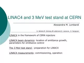
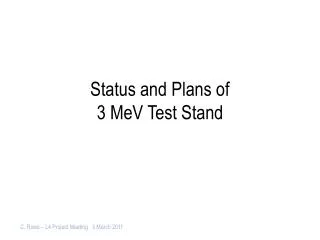
3 MeV test stand measurement plans. A. Lombardi for the LINAC4 team. Scope. Validate Source and LEBT design RFQ design Chopper. Source 45 keV. Chopper. Diagnostic line. RFQ 3 MeV. LINAC end-to-end. Location and causes of e growth and losses:

E N D
3 MeV test stand measurement plans A. Lombardi for the LINAC4 team BCC 41 - 3MeV test stand measurements
Scope • Validate • Source and LEBT design • RFQ design • Chopper Source 45 keV Chopper Diagnostic line RFQ 3 MeV
LINAC end-to-end Location and causes of e growth and losses: LEBT solenoids (divergent beam from the source). 45 keV MEBT transport (abrupt change of phase advance). 3 MeV BOTH ARE UNAVOIDABLE but they must be controlled
Emittance 0-3 MeV Symmetry x,y in LEBT, if source is symmetric Losses in the RFQ, emittance decreases Losses and emittance increase when matching to the DTL
bench Spectrometer (0.2 %) Slit and Grid Emittance ToF (calibration) Bunch Shape Monitor Halo Monitor (chopping eff.) Transformers Feshenko EDMS – 1004908 G. Bellodi BCC 41 - 3MeV test stand measurements
Measurement plan – 1/2 BCC 41 - 3MeV test stand measurements
Measurement plan – 2/2 BCC 41 - 3MeV test stand measurements
MOST IMPORTANT MEAS Pencil beam All elements on Chooper on (top) Chopper off (bottom) With this we validate : • Chopper voltage • Optics we do not validate : • Space charge • Rise/fall time BEAM AT THE ws JUST BEFORE THE INLINE DUMP
Measurement 2011 – p from DESY OP DAY - 26th January 2012 Archamps
Protons • Already discussed – EDMS 1096658 • Measurement with Desy source in proton mode (2011) gave an excellent insight into LEBT dynamics and solenoid modelling To be done before protons are usable : • optimise to reach a min of 50-60 mA after the first solenoid, • measure emittance vs. solenoid settings (5-10) and back-trace to source input : create a beam for simulating/optimising the whole test stand. BCC 41 - 3MeV test stand measurements
Sharing the test stand- proposal(change over takes ½ day to 1 day) • Run in proton mode until the emittance metre has to be dismantled • Source development till RFQ ready for beam • Share 2:1 between 3 MeV measurements and source development, over 3 weeks period or as best convenient. • DO NOT FORGET COMMISSIONING TIME FOR DIAGNOSTICS BCC 41 - 3MeV test stand measurements
Proposal - • 3 MeV beam commissioning must be done in 2 sessions/day on the basis 5 days/week . E.g. 7:00- 14:00 and 14-21 • We (BD team) are 3 staff + 3 visitors • Daily brief meeting with the people on the field + 1 by-weekly meeting in the control room to take decisions – CALLED BY GB • Need experts available as much as possible (in 2011 we “took it easy” but it took 6 months to measure the LEBT!) BCC 41 - 3MeV test stand measurements
Something has to give… • Laser stripping measurements ( make sure that BI is made aware) • Halo measurements under different matching • Matching to the DTL • Buncher optimisation • Pencil beam scans • Calibration of TOF vs. spectrometre…….. And many more The time presently allocated for commissioning in the tunnel is not sufficient-need 6 months We should repeat the measurements after the RFQ in the tunnel BCC 41 - 3MeV test stand measurements