LED Wafer Processing
LED Wafer Processing. By Chia-how Michael Liu Group #6. Objective . Learn to use the different machines. Learn the fabrication process. Maximize infrared light intensity from LED. Revisions. Original plan: Design mask for wafer-bonded LED. Wafer-bonded LED not ready.

LED Wafer Processing
E N D
Presentation Transcript
LED Wafer Processing By Chia-how Michael Liu Group #6
Objective • Learn to use the different machines. • Learn the fabrication process. • Maximize infrared light intensity from LED.
Revisions • Original plan: Design mask for wafer-bonded LED. • Wafer-bonded LED not ready. • Instead, focus on processing.
Processing on two wafers • Wafer with a bare substrate (test wafer to confirm processing correct) • Wafer with p-n junction via MBE growth (will be used for probing) p n n+ substrate n+ substrate Actual wafer Test wafer
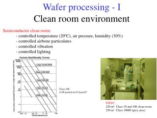
1. Silicon Nitride deposition • Clean wafer. • Use the PECVD Nitride System to deposit silicon nitride (SiNx). • Deposit 1000Å of SiNx. • Deposition should be completed within an hour; most of the time will be spent for safety cleaning within the machine. SiNx p n n+ substrate
2. Photolithography • Ultrasonic clean. • Dry wafer. • Adjust the settings of the photoresist (PR) machine to: Slow speed for 3 sec. at 1000 rpm High speed for 30 sec. at 5000 rpm • Apply PR and spin. • Check for even distribution. If good, then softbake. If not, then redo photolithography. PR SiNx p n n+ substrate
3. Mask exposure UV light • Use the Karl Suss aligner to expose wafer to the TLM mask. • Check for rings; they indicate contact. • Expose to UV light for 15 seconds. • Develop the chip for one minute using 327 MIF developer. • Check under the microscope for good exposure and PR removal. If exposure bad, redo photolithography. If PR not removed where the mask is, develop for a longer time. Mask PR SiNx p n n+ substrate
Mask design . . . . . .
4. Etching • Etching removes the SiNx not covered by PR. • Use HF buffer. • Dip the wafer into the HF for one minute. • Check under microscope for thorough etch. PR SiNx p n n+ substrate
5. Deposit metal for contact • Deposit metal using the Cooke evaporator. • Pressure has to be less than 8*10-7 Torr. Deposit on the top side: Ti (200Å, e-beam) Pt (200Å, e-beam) Au (400Å, thermal) • Total time of about 2.5 hrs. • Repeat process for bottom side. • For the bottom side, deposit: AuGe (500Å, thermal) Ni (200Å, e-beam) Au (800Å, e-beam) Ti/Pt/Au PR SiNx p n n+ substrate AuGe/Ni/Au
6. Lift-off and Annealing • Lift-off removes the remaining PR and the metal on top of it. • Use ultrasonic agitation with acetone. • Anneal using hydrogen flow. Ti/Pt/Au Ti/Pt/Au PR SiNx p n n+ substrate AuGe/Ni/Au
7. Testing • Test at the probe station. • Test the I-V characteristics. • Use an infrared detector to test for infrared light. • Some light also comes from thermal heat. • Infrared light intensity: 15 uW. Wafer top view with mask design metal probe SiNx Side view top probe bottom probe processed chip probe stage
Ideal diode IV graph Forward region Reverse bias region Reverse bias breakdown region
Sources of error • The growth condition may not be right (p-n junction is not good). • Sample backside needs to be polished. • Annealing condition for ohmic contacts.
Accomplishments • Satisfied objectives. • Thorough understanding of the fabrication process. • LED emitted infrared light.
Challenges • Cooke evaporator broken for much of the summer. • Thermal heat also emitted. • Processing takes time—8 weeks is too short for thorough processing and testing.
Further research • Maximize light intensity by trying other types of substrates and metals. • More analysis to test wafer’s properties. • Will continue research in the fall: design mask for wafer-bonded LED.
Acknowledgments Advisor: Kuo-lih Chang Prof: K.C. Hsieh TA: Mark Wiegert