Download
1 / 60
610 likes | 1.27k Vues
Design of Arithmetic Circuits – Adders, Subtractors, BCD adders. Week 6 and 7 (Lecture 2 of 2). What we are going to discuss?. Design of Half Adder – Different ways of implementation Design of Full Adder – using two half adders, using only NAND or using only NOR gates

E N D
Design of Arithmetic Circuits – Adders, Subtractors, BCD adders Week 6 and 7 (Lecture 2 of 2)
What we are going to discuss? • Design of Half Adder – Different ways of implementation • Design of Full Adder – using two half adders, using only NAND or using only NOR gates • Design of Half Subtractor • Design of Full Subtractor-using two half subtractors • Construction of 2-bit, 4-bit parallel binary adders, 4-bit parallel binary subtractors, 4 bit parallel binary adder/subtractor circuits • Construction of Carry lookahead adder • BCD addition – Design of 8421 BCD adder circuit
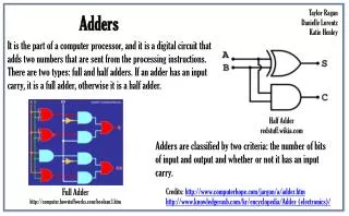
Half-Adder • This circuit needs 2 binary inputs and 2 binary outputs. • The input variables designate the augend and addend bits:the output variables produce the sum and carry. Inputs Carry Sum • X Y C S • 0 0 0 0 • 0 1 0 1 • 1 0 0 1 • 1 1 1 0
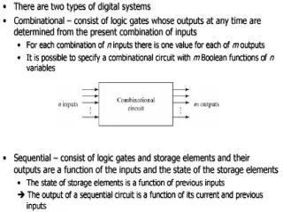
Full-Adder • Is a combinational circuit that forms the arithmetic sum of 3 bits. • Consists of 3 inputs and 2 outputs. • When all input bits are 0 , the output is 0. • The output S equal to 1 when only one input is equal to 1 or when all 3 inputs are equal to 1. • The C output has a carry of 1 if 2 or 3 inputs are equal to 1.
Full Adder Truth Table X’Y’Z X’YZ’ X’YZ XY’Z’ XY’Z XYZ’ XYZ XYZ
Simplification of Boolean expressions for Full adder C=XY+XZ+YZ S=XY’Z’ +X’YZ’ + XYZ + X’Y’Z
Implementation of Full Adder using AND-OR Gate Network
Implementation of Full Adder using Two Half Adders (1)… C= XY’Z + X’YZ + XYZ’+XYZ = XY’Z + X’YZ + XY(Z’+Z) = XY’Z + X’YZ + XY = Z(XY’ + X’Y) + XY = Z (X Y) + XY S=XY’Z’ +X’YZ’ + XYZ + X’Y’Z = Z’ (XY’+X’Y) + Z (XY + X’Y’) = Z’ (XY’ + X’Y) + Z (XY’ + X’Y)’ = Z (X Y)
Implementation of Full Adder using Two Half Adders (2) X S Y Z C
Implementation of Full Adder using onlyNAND gates (1)…Boolean expressions in NAND form
Implementation of Full Adder using onlyNAND gates (2) - Logic Diagram X Y Z S C
Full Adder Truth Table (X+Y+Z) (X+Y+Z) (X+Y+Z’) (X+Y’+Z) (X+Y’+Z’) (X’+Y+Z) (X’+Y+Z’) (X’+Y’+Z)
Implementation of Full Adder using onlyNOR gates (1)…Boolean expressions in NOR form
Implementation of Full Adder using onlyNOR gates (2)-Logic Diagram
HALF SUBTRACTORS Half subtractor accepts two binary digits as input (Minuend and Subtrahend) and produces two outputs, a Difference bit (Di) and Borrow bit (B0). Difference Borrow 0 0 = 0 0 0 1 = 1 1 1 0 = 1 0 1 1 = 0 0
The truth table and the logic symbol for half subtractor A’B AB’ A’B
Boolean expressions for half subtractor The difference (Di) output column of the truth table is an XOR operation. Di = AB The Boolean expression for the borrow (B0) output is
FULL SUBTRACTOR-Truth Table and Logic Symbol The FS accepts three inputs including a borrow input (Bin) and produces a difference output (Di) and a borrow output (B0).
Boolean Expressions for Full Subtractor A’B’Bin A’B’Bin A’BBin’ A’BBin’ A’BBin AB’Bin’ ABBin ABBin
Boolean Expressions for Full Subtractor Di A’B’Bin + A’BBin’ + AB’Bin’ + ABBin = A’(B’Bin + BBin’) + A(B’ Bin’ + BBin) = A’(B Bin) + A(B Bin)’ = A B Bin B0 A’B’Bin + A’BBin’ + A’BBin + ABBin = A’B’Bin + ABBin + A’B(Bin + Bin’) = Bin( A B)’ + A’B
Boolean Expressions for Full Subtractor Difference output of the FS can be given by Di = AB Bin The borrow output of the FS can be derived by the truth table as follows.
LOGIC DIAGRAM FOR FULL SUBTRACTOR • Di = AB Bin
FULL SUBTRACTOR USING TWO HALF-SUBTRACTORS AB • Di = AB Bin
PARALLEL ADDER • Parallel Adder is a digital circuit that produces the arithmetic sum of 2 binary numbers. • Constructed with full adders connected in cascade, with output carry from each full adder connected to the input carry of next full adder in the chain. • The augend bits of A and the addend bits of B are designated by subscript numbers from right to left, with subscript 1 denoting the least significant bit. • The carries are connected in a chain through the full adders.
2- Bit Parallel Adder (1)… • LSB of two binary numbers are represented by A1 and B1. • The next higher bit are A2 and B2. The resulting three sum bits are 1, 2 and CO, in which the CO becomes MSB. • The carry output CO of each adder is connected as the carry input of the next higher order. A2A1 + B2B1 C021
2-BIT PARALLEL ADDER USING A HALF ADDER AND A FULL ADDER (2)… A2A1 + B2B1 C021
2-BIT PARALLEL ADDER USING TWO FULL ADDERS (3) A2A1 + B2B1 C021
Four Bit Parallel Adders (1)… • An n-bit adder requires n full adders with each output connected to the input carry of the next higher-order full adder. • A four bit parallel adder using 3 FA and 1 HA is shown. • Halfadder adds the 1s column A1 and B1. The 2s, 4s and 8s columns being added by three FA. • The carry output of each adder is connected to the carry input of next adder called as internal carries.
Four Bit Parallel Adders (2)-An example… Where Ai = 10112 Bi = 00112
Logic Symbol Of Four Bit Parallel Adder (4)… The 4 bit parallel adders can be used to form 8 bit, 12 bit, 16 bit and 32 bit parallel adders.
2-BIT PARALLEL SUBTRACTOR Here the least significant bit (LSB) of the two numbers are represented by A1 and B1 and the next higher bit are A2 and B2. The BO of 1s HS is connected to Bin 2s FS. The subtractor produces two difference bits D1 and D2.
Four Bit Parallel Subtractor using Half and Full Subtractors
Four Bit Parallel Subtractor using Full Adders (1)… • Parallel adders can be used to perform binary subtraction because the subtraction is addition in the 2’s complement form of binary number. • The four bit subtractor using four Full Adder is shown.
Four Bit Parallel Subtractor using Full Adders (2)…
Four Bit Parallel Subtractor using Full Adders (3) • The four inverters change the binary subtrahend to its 1’ complement form i.e 1 to 0 and 0 to 1. • The high input at Cin, LSB makes the binary subtrahend to 2s complement form. • Then minuend and 2’s complement form of subtrahend are added. The output line C0 of fourth Full adder is the overflow output which is discarded.
4 bit Parallel Adder / Subtractor Circuit (2) • 4 bit parallel adder / subtractor Circuit can be constructed using Full Adders and XOR gates as shown. • The logic circuit has an additional input called the control input, which determines the addition or subtraction. • If this control input is logic 0, the all four XOR gates have no effect on the data on the input line B. • IF Cin of the first Full Adder is held low, it works as a four bit parallel adder • When the control input is at logic 1 the XOR gates work as a inverter and the circuit performs as four bit parallel subtractor
Carry Propagation (1)… • The addition of 2 binary numbers in parallel implies that all the bits of the augend and addend are available for computation at the same. • The signal must propagate through the gates before the correct output sum is available in the output terminals. • The total propagation time is equal to the propagation delay of a typical gates times the number of gate levels in the circuit.
Carry Propagation (2) • The number of gate levels for the carry propagation can be found from the circuit of the full adder. • In the figure for full adder, the input and output variables use the subscript i to denote a typical stage in the adder. • The signals at Pi and Gi settle to their steady state value after they propagate through their respective gates. • These 2 signals are common to all full adders and depend only on the input augend and addend bits.
Full Adder Circuit with P and G (2) • If we define two new binary variables Pi = Ai Bi Gi = Ai Bi Then output sum and carry can be expressed as Si = Pi Ci Ci+1 = Gi +PiCi • Gi is called a carry generate and it produces a carry of 1 when both Ai and Bi are 1, regardless of the input carry Ci • Pi is called a carry propagate because it is the term associated with the propagation of the carry from ci to ci+1.
Carry Lookahead Generator (1)…-Boolean Expressions C0= input carry C1=G0+P0C0 C2=G1 +P1C1 = G1+P1(G0+P0C0) = G1+P1G0+P1P0C0 C3=G2+P2C2=G2+P2G1+P2P1G0+P2P1P0C0 C3 does not have to wait for C2 and C1 to propagate , in fact C3 is propagated at the same time as C1 and C2.
4 bit adder with carry lookahead (1)… • Each sum output requires 2 exclusive OR gates. • The output of the first exclusive OR gate generate the Pi variable and the AND gate generate the Gi variable. • The carries are propagated through the carry lookahead generator and applied as inputs to the second exclusive OR gate. • All output carries are generated after a delay through two levels of gates. • Thus , output S1 though S3 have equal propagation delay times.