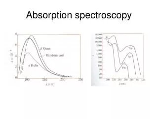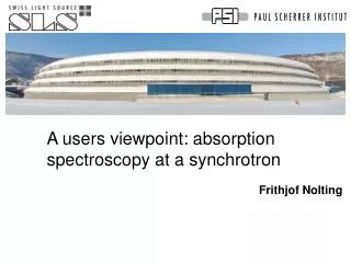
A users viewpoint: absorption spectroscopy at a synchrotron
200 likes | 331 Vues
A users viewpoint: absorption spectroscopy at a synchrotron. Frithjof Nolting. (1). (0). Ferromagnet. Ferromagnet. Antiferromagnet. Magnetic data storage and recording. GMR Element. Top layer “free” can be switched. Bottom layer “pinned” Hard layer or Exchange coupling.

A users viewpoint: absorption spectroscopy at a synchrotron
E N D
Presentation Transcript
A users viewpoint: absorption spectroscopy at a synchrotron Frithjof Nolting
(1) (0) Ferromagnet Ferromagnet Antiferromagnet Magnetic data storage and recording GMR Element Top layer “free” can be switched Bottom layer“pinned” Hard layer or Exchange coupling Low resistance high resistance Hard disk head MRAM
How? - Different models for AFM/FM coupling exist. - Different assumptions on AFM structure lead to complete different results. - Spin arrangement at the interface is important • High Spatial Resolution • Elemental Sensitivity • Ferromagnetic Contrast • Antiferromagnetic Contrast • Surface/Interface Sensitivity FM Interface AFM X-ray absorption spectroscopy (XAS) with spatial resolution Photoemission Electron Microscope (PEEM)
hn I (nA) Energy valence E band F n h (x-ray) ~ ~ core 2p 3/2 level 2p1/2 Photoemission Electron Microscope analyzer Magnetic lenses e- X-rays 20 kV 16° ELMITEC GmbH • Sensitive to: • elemental composition • chemistry • structural parameters • electronic structure • magnetic properties
5 µm 5 µm S Magnetic microscopy XMCD (X-ray Magnetic Circular Dichroism) Co XMLD (X-ray Magnetic Linear Dichroism) LaFeO3 E J. Stöhr et al. Science 1993 A. Scholl et al. Science 2000 F. Nolting et al. Nature 2000
XMCD 1.5 nm Ru Magnetic field 3 nm Co Left and right circularly polarized light 50 nm NiO 30° 3 nm Co Exchange biased Co/NiO multilayer EPU beamline 4 at ALS Hysteresis of Co and NiO . . XMCD spectra – switching polarization Pinned Moments ? H. Ohldag, A. Scholl, F. Nolting, E. Arenholz, S. Maat, A.T. Young, M. Carey, and J. Stöhr, Phys. Rev. Lett. 91(1), 017203/1-4 (2003).
Ratio of A/B Antoine Barbier et al User experiment at SLS, July 2004
SIM Beamline Layout Front end Microscope User endstation Refocusingoptics ID1 ID2 Monochromator Chopper Prepchamber • UndulatorT. Schmidt • 2 Elliptical undulators • Pure permanent magnet • 95eV < hn < 2000eV • >1019 photons/s/mrad2/mm2/400mA • 100 % circular polarization[125 - 900 eV]reduced on higher harmonics • Hor. & vert. linear polar. • EndstationC. Quitmann & F. Nolting • SLS endstation: • PEEM & LEEMDx~25 - 50nm spatialDE~150meV energy • Sample Prep chamber • User endstation • OpticsU. Flechsig • Plane grating monochromator • E/DE > 8000 • <5% 2nd order light • Switch helicity • Focus 30x100mm2
How do we measure Magnet TEY Reference signal Sample signal Sample = Norm Reference Moving gap and monochromator, stop, measure (1s – 1minute), moving …
How do we measure • Change polarization and repeat • Take difference of spectra Absorption spectrum requires frequent moving of gap and shift must not effect other beamlines transparent!
Modes for switching the polarization switching by moving phase 120 s move up 56 mm circ plus circ minus switching by moving the gap 1s - 8 s move 2 mm tuned detuned detuned tuned switching by using a chopper 100 Hz move 0 mm chopper
Alignment of IDs - Horizontal 2. Horizontal overlap at focus of experiment ID2 Intensity Closed bump using chicane magnets Horizontal position 1. Horizontal overlap at Frontend 2D Frontend scan ID1 ID2 ID2 Asymmetric bump
Alignment of IDs - Vertical 3. Vertical (energy) overlap at focus of experiment Absorption spectrum schematic ID1 Intensity mono Exit slit source Photon energy ID2 Intensity ID2 Intensity 778.3 eV not yet finished !
Beam variation - Noise horizontal movement intensity variation XAS normalization reduces it by a factor of 10-100 PEEM no normalization days no problem hours no problem sec - minutes bad mili seconds ok vertical movement energy variation no normalization! days no problem hours bad seconds bad mili seconds ok 10 μm about 2% 10 μm about 10 meV
Energy shift Energy shift of 10 meV Identical spectra 1 %
Orbit feedback Fast orbit feedback slow orbit feedback Orbit correctors? beam position in ID (Bergoz) X-ray position in beamline Shift and gap
Orbit feedback – effect on measurement Normalized signal, circular plus Difference circular plus and minus Increased noise!!!
Slow Orbit feedback Circular minus Circular plus Orbit correctors? beam position in ID (Bergoz) X-ray position in beamline Shift and gap
Slow Orbit feedback Not transparent ! 10 μm
Summary We can do great measurements at SLS • Transparent IDs are essential! Very difficult to make an EPU transparent. Have to rely on Orbit feedback • For the measurement “no” difference between slow and no Orbit feedback • Critical time scale second – hour (10 Hz – 0.0001 Hz) Intensity variation 0.1% 0.5 μm energy variation 1meV 1 μm • Slow Orbit feedback is not sufficient Fast Orbit feedback is great