Intelligent Vision Processor
Intelligent Vision Processor. John Morris Computer Science/ Electrical & Computer Engineering, The University of Auckland. “Iolanthe II” rounds Channel Island - Auckland-Tauranga Race, 2007. Intelligent Vision Processor. Applications Robot Navigation


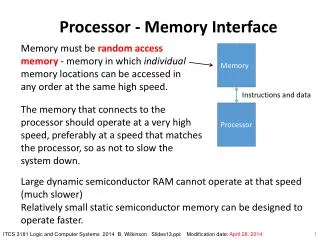
Intelligent Vision Processor
E N D
Presentation Transcript
Intelligent Vision Processor John Morris Computer Science/Electrical & Computer Engineering,The University of Auckland “Iolanthe II” rounds Channel Island -Auckland-Tauranga Race, 2007
Intelligent Vision Processor Applications Robot Navigation Collision avoidance – autonomous vehicles Manoeuvring in dynamic environments Biometrics • Face recognition Tracking individuals Films Markerless motion tracking Security Intelligent threat detection Civil Engineering Materials Science Archaeology
Intelligent Vision • Our vision system is extraordinary • Capabilities currently exceed those of any single processor • Our brains • Operates on a very slow ‘clock’: • kHz region • Massively parallel • >1010 neurons can compute in parallel • Vision system (eyes) can exploit this parallelism • ~3 x 10⁶ sensor elements (rods and cones) in human retina
Intelligent Vision • Matching and recognition • Artificial intelligence systems are currently not in the race! For example • Face recognition • We can recognize faces • From varying angles • Under extreme lighting conditions • With or without glasses, beards, bandages, makeup, etc • With skin tone changes, eg sunburn • Games • We can strike balls travelling at > 100km/h • and • Direct that ball with high precision
Human vision • Uses a relatively slow, but massively parallel processor (our brains) • Able to perform tasks • At speeds • and • With accuracy beyond capabilities of state-of-the-art artificial systems
Intelligent Artificial Vision • High performance processor • Too slow for high resolution (Mpixel+) imagein real time (~30 frames per second) • Useful vision systems • Must be able to • Produce 3D scene models • Update scene models quickly • Immediate goal: 20-30Hz to mimic human capabilities • Long term goal: >30 Hz to provide enhanced capabilities • Produce accurate scene models
Intelligent Artificial Vision Use human brain as the fundamental model We know it works better than a conventional processor! We need
Lens Eyeball Retina Human Vision Systems • Higher order animals all use binocular vision systems • Permits estimation of distance to an object • Vital for many survival tasks • Hunting • Avoiding danger • Fighting predators • Distance (or depth) computed by triangulation P P’’ P’ P’-P’’ is the disparity It increases as P comes closer
Human Vision Systems • Higher order animals all use binocular vision systems • Permits estimation of distance to an object • Vital for many survival tasks • Hunting • Avoiding danger • Fighting predators • Distance (or depth) computed by triangulation P P’’ P’ P’-P’’ is the disparity Increases as P comes closer
P Opticalaxis P’’ P’ Fixationpoint P F P’’ P’ Artificial Vision • Evolution took millions of years to optimize vision • Don’t ignore those lessons! • Binocular vision works • Verging optics • Human eyes are known to swivel to ‘fixate’ on an object of interest
Real vs Ideal Systems • Real lenses distort images • Distortion must be removed for high precision work! • Easy • but • Conventional technique uses iterative solution • Slow! • Faster approach needed for real time work Image of a rectangular gridwith a real lens
Why Stereo? • Range finders give depth information directly • SONAR • Simple • Not very accurate (long l) • Beam spread Low spatial resolution • Lasers • Precise • Low divergence High spatial resolution • Requires fairly sophisticated electronics • Nothing too challenging in 2008 Why use an indirect measurement when direct ones are available?
Why Stereo? • Passive • Suitable for dense environments • Sensors do not interfere with each other • Wide area coverage • Multiple overlapping views obtainable without interference • Wide area 3D data can be acquired at high rates • 3D data aids unambiguous recognition • 3rd dimension provides additional discrimination • Textureless regions cause problems but • Active illumination can resolve these • Active patterns can use IR (invisible, eye-safe) light
Artificial Vision - Challenges • High processor power • Match parallel capabilities of human brain • Distortion removal • Real lenses always show some distortion • Depth accuracy • Evolution learnt about verging optics millions of years ago! • Efficient matching • Good corresondence algorithms
Artificial Vision • Simple stereo systems are being produced • Point Grey, etc • All use canonical configuration • Parallel axes, coplanar image planes • Computationally simpler • High performance processor doesn’t have time to deal with the extra computational complexity of verging optics Point Grey Research Trinocular vision system
Artificial System Requirements • Highly Parallel Computation • Calculations are not complex but • There are a lot of them in megapixel+ ( >106 ) images! • High Resolution Images • Depth is calculated from the disparity • If it’s only a few pixels, then depth accuracy is low • Basic equation (canonical configuration only!) Baseline Focal Length Depth, z = b f d p Pixel size Disparity
Artificial System Requirements • Depth resolution is critical! • A cricket* player can catch a 100mm ball travelling at 100km/h • High Resolution Images Needed • Disparities are large numbers of pixels • Small depth variations can be measured but • High resolution images increase the demand for processing power! *Strange game played in former British coloniesin which a batsmen defends 3 small sticksin the centre of a large field against a bowler whotries to knock them down!
Artificial System Requirements • Conventional processors do not have sufficient processing power • but Moore’s Law says • Wait 18 months and the power will have doubled but • The changes that give you twice the poweralso give your twice as many pixels in a rowand four times as many in an image! Specialized highly parallel hardwareis the only solution!
FPGA Hardware • FPGA = Field Programmable Gate Array • ‘Soft’ hardware • Connections and logic functions are ‘programmed’ in much the same way as a conventional von Neuman processor • Creating a new circuit is about as difficult as writing a programme! • High order parallelism is easy • Replicate the circuit n times • As easy as writing a for loop!
FPGA Hardware • FPGA = Field Programmable Gate Array • ‘Circuit’ is stored in static RAM cells • Changed as easily as reloading a new program
FPGA Hardware • Why is programmability important? • or • Why not design a custom ASIC? • Optical systems don’t have the flexibility of a human eye • Lenses fabricated from rigid materials • Not possible to make a ‘one system fits all’ system • Optical configurations must be designed for each application • Field of view • Resolution required • Physical constraints • … • Processing hardware has to be adapted to the optical configuration • If we design an ASIC, it will only work for one application!!
Stereo Correspondence Can you find all the matching points in these two images? “Of course! It’s easy!” The best computer matching algorithms get 5% or more of the points completely wrong! …and take a long time to do it!They’re not candidates for real time systems!!
Stereo Correspondence • High performance matching algorithms are global in nature • Optimize over large image regions using energy minimization schemes • Global algorithms are inherently slow • Iterate many times over small regions to find optimal solutions
Correspondence Algorithms • Good matching performance, global, low speed • Graph-cut, belief-propagation, … • High speed, simple, local, high parallelism, lowest performance • Correlation • High speed, moderate complexity, parallel, medium performance Dynamic programming algorithms
Points along these lineshave the same disparity Stereo Configuration • Canonical configuration – Two cameras with parallel optical axes • Rays are drawn through each pixel in the image • Ray intersections represent points imaged onto the centre of each pixel Depthresolution • but • To obtain depth information, a point must be seen by both cameras, ie it must be in the Common Field of View
Stereo Camera Configuration • Now, consider an object of extent, a • To be completely measured, it must lie in the Common Field of View • but • place it as close to the camera as you can so that you can obtain the best accuracy, say at D • Now increase b to increase the accuracy at D • But you must increase D so that the object stays within the CFoV! • Detailed analysis leads to an optimum value ofb a a D b a
Increasing the baseline Increasing the baseline decreases performance!! % good matches Images: ‘corridor’ set (ray-traced) Matching algorithms: P2P, SAD Baseline, b
Increasing the baseline Examine the distribution of errors Increasing the baseline decreases performance!! Standard Deviation Images: ‘corridor’ set (ray-traced) Matching algorithms: P2P, SAD Baseline, b
Increased Baseline Decreased Performance • Statistical • Higher disparity range • increased probability of matching incorrectly - you’ve simply got more choices! • Perspective • Scene objects are not fronto-planar • Angled to camera axes • subtend different numbers of pixels in L and R images • Scattering • Perfect scattering (Lambertian) surface assumption • OK at small angular differences • increasing failure at higher angles • Occlusions • Number of hidden regions increases as angular difference increases • increasing number of ‘monocular’ points for which there is no 3D information!
Evolution • Human eyes ‘verge’ on an object to estimate its distance, ie the eyes fix on the object in the field of view Configuration commonly used in stereo systems Configuration discovered by evolution millions of years ago Note immediately that the CFoV is much larger!
Look at the optical configuration! • If we increase f, then Dmin returns to the critical value! Original f Increase f
Depth Accuracy - Verging axes, increased f Now the depth accuracy has increased dramatically! Note that at large f, the CFoV does not extend very far!
Summary: Real time stereo • General data acquisition is: • Non contact • Adaptable to many environments • Passive • Not susceptible to interference from other sensors • Rapid • Acquires complete scenes in each shot • Imaging technology is well established • Cost effective, robust, reliable • 3D data enhances recognition • Full capabilities of 2D imaging system • Depth data • With hardware acceleration • 3D scene views available for • ControlMonitoring • in real time • Rapid response rapid throughput Host computer is free to process complex control algorithms Intelligent Vision Processing Systems which can mimic human vision system capabilities!
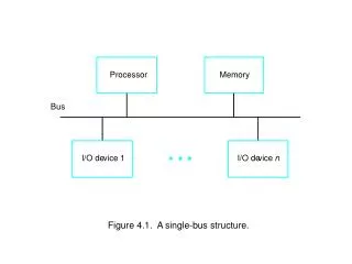
System Architecture FPGA L Camera SerialInterface Firewire/GigE/CameraLink Line BuffersDistortion Removal Image Alignment RCamera PC Host Higher orderInterpretation Control Signals CorrectedImages Stereo Matching Disparity Depth DepthMap
Distortion removal • Image of a rectangular grid from camera with simple zoom lens • Lines should be straight! • Store displacements of actual image from ideal points in LUT • Removal algorithm • For each ideal pixel position • Get displacement to real image • Calculate intensity of ideal pixel (bilinear interpolation)
Distortion Removal • Fundamental Idea • Calculation of undistorted pixel position • Simple but slow • Not suitable for real time but • It’s the same for every image! • So, calculate once! • Create a look up table containing ideal actual displacements for each pixel ud = uud(1+k2+k4+..)r2 r2 = (uud+vud)2
Distortion Removal • Creating the LUT • One entry (dx,dy) per pixel • For a 1 Mpixel image needs 8 Mpixels! • Each entry is a float – (dx,dy) requires 8 bytes • However, distortion is a smooth curve • Store one entry per n pixels • Trials show that n=64 is OK for severely distorted image • LUT row contains 210 / 2 6 = 24 = 16 entries • Total LUT is 256 entries • Displacement for pixel j,k • dujk = (j mod 64) * duj/64,k/64 • duj/64,k/64 is stored in LUT • Simple, fast circuit Since the algorithm runs along scan lines,this multiplication is done by repeated addition
Alignment correction • In general, cameras will not be perfectly aligned in canonical configuration • Also, may be using verging axes to improve depth resolution • Calculate locations of epipolar lines once! • Add displacements to LUT for distortion!
Real time 3D data acquisition • Real time stereo vision • Implemented Gimel’farb’s Symmetric Dynamic Programming Stereo in FPGA hardware • Real time precise stereo vision • Faster, smaller hardware circuit • Real time 3D maps • 1% depth accuracy with 2 scan line latency at 25 frames/se System block diagram: lens distortion removal,misalignment correction and depth calculator Output is stream of depth values: a 3D movie!
Real time 3D data acquisition • Possible Applications • Collision avoidance for robots • Recognition via 3D models • Fast model acquisition • Imaging technologynot scanning! • Recognition of humans without markers • Tracking objects • Recognizing orientation, alignment • Process monitoring eg Resin flow in flexible (‘bag’) moulds • Motion capture – robot training System block diagram: lens distortion removal,misalignment correction and depth calculator Output is stream of depth values: a 3D movie!
FPGA Stereo System Parallel Host Interface FirewireCables FPGA AlteraStratix FirewirePhysical Layer ASIC FirewireLink Layer ASIC FPGA Prog Cable
Summary • Challenges of Artificial Vision Systems • Real-time Image processing requires compute power! • Correspondence (Matching) • Depth accuracy • Evolution Lessons • Emulate parallel processing capability of humanbrain • Use verging optics