Comprehensive Overview of MVD Assembly and Cooling System Design Progress and Requirements
140 likes | 269 Vues
This document provides a detailed account of the MVD assembly process, highlighting the completion of critical frame components and dimension testing. Ancillaries for frames are finalized, and machining stages outlined. The assembly sequence, fixing points for sub-structures, and services routing are clearly defined. An overview of the MVD pixel-cooling system, along with its thermal analysis results, is included. The aim is to achieve necessary rigidity with deformation targets and optimize cooling for enhanced performance. All outlined tasks must be completed as specified.

Comprehensive Overview of MVD Assembly and Cooling System Design Progress and Requirements
E N D
Presentation Transcript
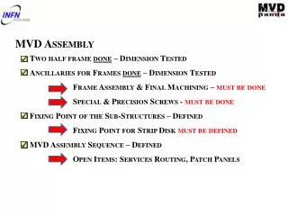
MVD Assembly • Two half frame done – Dimension Tested • Ancillaries for Frames done – Dimension Tested • Frame Assembly & Final Machining – must be done • Special & PrecisionScrews - must be done • Fixing Point of the Sub-Structures – Defined • Fixing Point for Strip Disk must be defined • MVD Assembly Sequence – Defined • Open Items: Services Routing, Patch Panels
MVD Integration • MVD Aligned & Fixed on Central Frame • Ref. Bosses: two options gluing/machining • Open Item: Central Frame Definition • Critical Point: Cross Pipe Position/Geometry • MVD Final Survey • Position of target point must be defined • MVD Services Routing • Tests must be defined • Patch Panel Position must be defined • Open Item: Services Routing Outside the Magnet
MVD Pixel-Mechanics Barrel & Disks Geometry Defined Barrel & Disks Assembly Procedure Defined but NOT TESTED Barrel & Disks Cooling Tubes Assembly Defined & TestedAssemblyTooling to be defined
Services Routing - Patch Panels Very preliminary PATCH PANELS OUTSIDE STT/TPC VOLUME – PIXEL DISKS PATCH PANELS INSIDE STT/TPC VOLUME – BARREL (PIXEL+STRIP) DIFFERENT PATH FOR CABLES AND TUBES CRITICITY!!!
CENTRAL FRAME DEFINITION CENTRAL FRAME DESIGN – TARGET: RIGIDITY TARGET: MAX DEFORMATION < 50μm 1ST STEP – CURRENT DESIGN 142 μm MVD SUPPORT AREA STATIC LOAD (CROSS PIPE+MVD+STT) M55J/ROHACELL/M55J+TITANIUM (CONNECTING PART )
CENTRAL FRAME DESIGN – TARGET RIGIDITY TARGET DEFORMATION < 50μm 2nd STEP – CENTRAL WINDOWS REMOVED 124 μm MVD SUPPORT AREA STATIC LOAD (CROSS PIPE+MVD+STT) M55J/ROHACELL/M55J+TITANIUM (CONNECTING PART )
CENTRAL FRAME DESIGN – TARGET RIGIDITY TARGET DEFORMATION < 50μm 3rd STEP – ALL WINDOWS REMOVED 104 μm MVD SUPPORT AREA STATIC LOAD (CROSS PIPE+MVD+STT) M55J/ROHACELL/M55J+TITANIUM (CONNECTING PART )
CENTRAL FRAME DEFINITION NEXT STEPS: RIBS EMBEDDED INTO THE STRUCTURE STRESS INDUCED TO THE CROSS-PIPE CONNECTING PARTS MADE BY EPM203 (EPOXY/GLASS) OR CYANATE/CARBON FIBRE
Mechanics TDR • DONE & WRITTEN • Frame: • Geometry, description. • Structural constraint. • Feasibility. • Barrel: • Geometry (sensors distribution) • Physical constraint. • Support and frame connection. • Disks: • Geometry (sensors distribution) • Physical constraint. • Frame connection. • TO BE DONE • Assembly sequence. • Assembly tools. • End stave electronics boards support definition. • Mechanical integration with strip parts (barrel & disks)
MVD Pixel-cooling carbon foam tested disks cooling Defined & tested, small disks to be optimized barrel cooling Defined &tested,to be optimized Open Item: test with master bond glue cfd simulation cooling plant-first drafs of pixel parts
Cooling TDR • DONE & WRITTEN • Pixel cooling system: • Pixel power • Thermal request • Working condition • Test on carbon foam (Young modulus and thermal conductivity at different radiation fields) • Disks cooling system: • Description • Fem analyses and test results on prototype • Pressure drop • Barrel cooling system: • Description • Fem analyses and test results on prototype • CFD simulation • Cooling plant: • Description • Pixel modularity • First drafts • TO BE DONE • Tests with Master Bond glue • Cooling for the End stave electronics boards • Strip part integration in the cooling plant • Final design of the cooling plant