DLX Processor
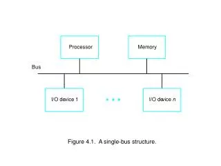
מבנה המחשב + מבוא למחשבים ספרתיים תרגול 13#. DLX Processor. ALU: Tasks performed in the control states. ALU: Control Signals. Signals that control the functionality of the ALU: ALUF[2:0] add (active during states: Decode, AluI, Adr.Comp., B.Taken,SavePC, JR, JALR).

DLX Processor
E N D
Presentation Transcript
מבנה המחשב + מבוא למחשבים ספרתייםתרגול 13# DLX Processor
ALU: Control Signals • Signals that control the functionality of the ALU: • ALUF[2:0] • add (active during states: Decode, AluI, Adr.Comp., B.Taken,SavePC, JR, JALR). • test (active during states: TestI). ALUF[2:0] – arithmetic / logical ALU operations 011 add 010 sub 110 and 101 or 100 xor ALUF[2:0] – test conditions 001 gt 010 eq 011 ge 100 lt 101 ne 110 le IR[2:0] = func[2:0] IR[28:26] = opcode[2:0]
OR(32) XOR(32) OR MUX(32) AND(32) INV MUX(32) Comparator(32) MUX(32) Next slide MUX(32) ALU: Implementation MUX(32)
ZERO(32) Comparator INV AND AND AND INV AND OR ALU: Implementation (cont’) OR
“Register B” • The instructions in which register B is loaded: • add • sub • and • or • xor • store Register B is not involved in computations during instructions in which it need not be loaded. Therefore, functionality is correct. Loading register B always (during Decode state), shortens the length of the path in the Control State Machine when executing instructions that need register B loaded.
“Register B” – Setting ce=1 or Removing The functionality of the DLX is not damaged due to (1) setting always Bce=1, or (2) Removing register B. • Consider the execution of the ith instruction: • The IR register outputs the ith instruction from the beginning of the Decode state (of the ith instruction) till the end of the first clock cycle in the Fetch state (of the i+1st instruction). • Therefore, the address of the register which is loaded into register B is not changed during the execution of the ith instruction. • Register B content is relevant only for R-type instructions (and Store inst.). • Therefore, we may consider the address of the register which is loaded into register B , as <RS2>. • We refer only to R-type instructions.
We may conclude: If (1) RS2 is not changed, and (2) The GPR Env. outputs the content of RS2, Then, Register B outputs the content of RS2 (=RS2 @ beginning of the ith instruction). • Two cases may damage the functionality: • The content of RS2 is changed. • May happen only during WBR state in which the output of reg. B (the content of RS2) is irrelevant anymore. Therefore, functionality is not damaged. • 2. The GPR Env. doesn’t output the content of RS2. • May happen only during a write operation to the GPR - Only during WBR state in which the output of reg. B (the content of RS2) is irrelevant anymore. Therefore, functionality is not damaged. Register B is necessary for minimizing the clock period.
Fetch Decode Shift0 WB-RS2+C WBR Expanding the instruction set: SWAP instruction For example: 000100 RTL Instruction Active Control Signals RD = RS2 RD = RS1