
Oscillators
E N D
Presentation Transcript
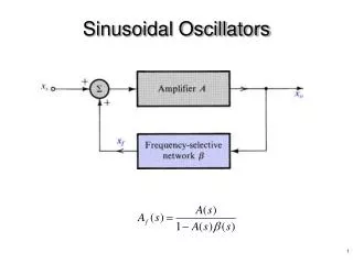
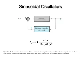
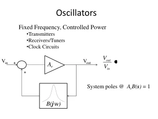
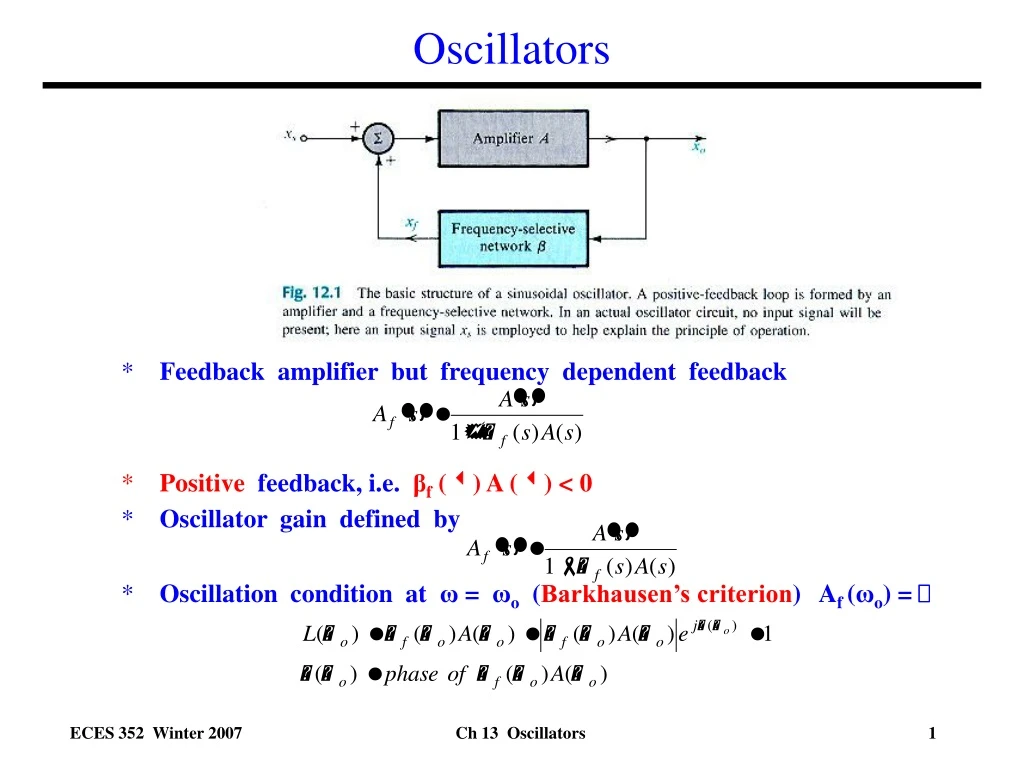
Oscillators • Feedback amplifier but frequency dependent feedback • Positive feedback, i.e. βf () A () < 0 • Oscillator gain defined by • Oscillation condition at ω= ωo (Barkhausen’s criterion) Af (ωo) = Ch 13 Oscillators
Wien Bridge Oscillator • Based on op amp • Combination of R’s and C’s in feedback loop so feedback factor βf has a frequency dependence. • Analysis assumes op amp is ideal. • Gain A is very large • Input currents are negligibly small (I+ I_ 0). • Input terminals are virtually shorted (V+ V_ ). • Analyze like a normal feedback amplifier. • Determine input and output loading. • Determine feedback factor. • Determine gain with feedback. • Shunt-shunt configuration. R2 R1 V0 Vi ZS If ZP Ch 13 Oscillators
Wien Bridge Oscillator Define R1 R2 V0 Vi ZS If ZP Output Loading Input Loading ZS ZS Z1 V0 = 0 Z2 Vi = 0 ZP ZP Ch 13 Oscillators
Wien Bridge Oscillator I1 I2 Amplifier gain including loading effects R2 R1 Vi V0 IS IS Z2 IS Z1 Feedback factor ZS If V0 ZP Ch 13 Oscillators
Wien Bridge Oscillator Oscillation condition Loop Gain Ch 13 Oscillators
Wien Bridge Oscillator - Example Oscillator specifications: o=1x10⁶ rad/s Ch 13 Oscillators
Wien Bridge Oscillator Final note:No input signal is needed. Noise at the desired oscillation frequency will likely be present at the input and when picked up by the oscillator when the DC power is turned on, it will start the oscillator and the output will quickly buildup to an acceptable level. Ch 13 Oscillators
Wien Bridge Oscillator • Once oscillations start, a limiting circuit is needed to prevent them from growing too large in amplitude Ch 13 Oscillators
Phase Shift Oscillator • Based on op amp using inverting input • Combination of R’s and C’s in feedback loop so get additional phase shift. Target 180o to get oscillation. • Analysis assumes op amp is ideal. Rf If IC3 IC2 IC1 V2 V1 VX C C C V0 IR1 R R IR2 Ch 13 Oscillators
Phase Shift Oscillator If Rf IC3 IC2 IC1 V2 V1 VX C C C V0 R R IR1 IR2 Example Oscillator specifications: o=1x10⁶ rad/s Note: We get 180o phase shift from op amp since input is to inverting terminal and another 180o from the RC ladder. Ch 13 Oscillators
Colpitts LC-Tuned Oscillator • Feedback amplifier with inductor L and capacitors C1 and C2 in feedback network. • Feedback is frequency dependent. • Aim to adjust components to get positive feedback and oscillation. • Output taken at collector Vo. • No input needed, noise at oscillation frequency o is picked up and amplified. • RB1 and RB2 are biasing resistors. • RFC is RF Choke (inductor) to allow dc current flow for transistor biasing, but to block ac current flow to ac ground. • Simplified circuit shown at midband frequencies where large emitter bypass capacitor CE and base capacitor CB are shorts and transistor capacitances (C and C) are opens. CB V0 CE Vi V0 Vi Ch 13 Oscillators
Colpitts LC-Tuned Oscillator • Voltage across C2 is just V • Neglecting input current to transistor (I 0), • Then, output voltage Vo is • KCL at output node (C) • Setting s = j AC equivalent circuit Assuming oscillations have started, then V≠ 0 and Vo ≠ 0, so sC2V V0 Iπ≈ 0 sC2V Ch 13 Oscillators
Colpitts LC-Tuned Oscillator • To get oscillations, both the real and imaginary parts of this equation must be set equal to zero. • From the imaginary part we get the expression for the oscillation frequency • From the real part, we get the condition on the ratio of C2/C1 Ch 13 Oscillators
Colpitts LC-Tuned Oscillator • Given: • Design oscillator at 150 MHz • Transistor gm = 100 mA/V, R = 0.5 K • Design: • Select L= 50 nH, then calculate C2, andthen C1 Example Ch 13 Oscillators
Summary of Oscillator Design • Shown how feedback can be used with reactive components (capacitors) in the feedback path. • Can be used to achieve positive feedback. • With appropriate choice of the resistor sizes, can get feedback signal in phase with the input signal. • Resulting circuit can produce large amplitude sinusoidal oscillations. • Demonstrated three oscillator circuits: • Wien Bridge oscillator • Phase Shift oscillator • Colpitts LC-Tuned oscillator • Derived equations for calculating resistor and capacitor sizes to produce oscillations at the desired oscillator frequency. • Key result: Oscillator design depends primarily on components in feedback network, i.e. not on the amplifier’s characteristics. Wien Bridge Oscillator Phase Shift Oscillator Colpitts LC-Tuned Oscillator Ch 13 Oscillators