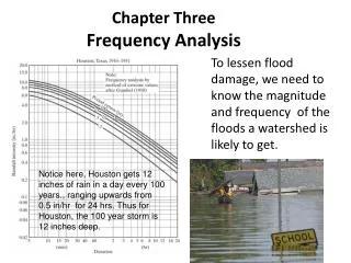
Frequency Analysis
Frequency Analysis. Objective. Frequency Analysis determines the likelihood of an event to occur The larger the number, the bigger the likelihood or chance for the event to occur. Techniques. Among others, two techniques are frequently used Event-Tree analysis Fault Tree Analysis.


Frequency Analysis
E N D
Presentation Transcript
Objective • Frequency Analysis determines the likelihood of an event to occur • The larger the number, the bigger the likelihood or chance for the event to occur.
Techniques • Among others, two techniques are frequently used • Event-Tree analysis • Fault Tree Analysis
Fault Tree is a method by which a particular undesired system failure mode can be expressed in terms of component failure modes and operator actions. The system failure mode to be considered is termed the “top event” and fault tree is developed in branches below this event showing it causes., connected by using logic gate Fault Tree Analysis
Event Tree Analysis An event tree is a visual representation of all the events which can occur in a system. The goal of an event tree is to determine the probability of an event based on the outcomes of each event in the chronological sequence of events leading up to it. As the number of events increases, the picture fans out like the branches of a tree. By analyzing all possible outcomes, you can determine the percentage of outcomes which lead to the desired result.
Example This event tree was constructed to analyze the possible outcomes of a system fire. The system has 2 components designed to handle this event: a sprinkler system and an automated call to the fire department. If the fire department is not notified, the fire will be mostly contained by the sprinkler system. If the sprinkler system fails as well, the system will be destroyed.
Failures in Process Industries Single Component Failure Data for failure rates are compiled by industry Single component or single action Multiple Component Failure Failures resulting from several failures and/or actions Failure rates determined using FTA
Failure Rates Data Instrument Faults/year Controller 0.29 Control valve 0.60 Flow measurements (fluids) 1.14 Flow measurements (solids) 3.75 Flow switch 1.12 Gas – liquid chromatograph 30.6 Hand valve 0.13 Indicator lamp 0.044 Level measurements (liquids) 1.70 Level measurements (solids) 6.86
Failure Rates Data Instrument Faults/year Oxygen analyser 5.65 pH meter 5.88 Pressure measurement 1.41 Pressure relief valve 0.022 Pressure switch 0.14 Solenoid valve 0.42 Stepper motor 0.044 Strip chart recorder 0.22 Thermocouple temperature meas. 0.52 Thermometer temperature meas. 0.027 Valve positioner 0.44
Failure Rates Data Some data are per hour
Frequency, Reliability and Probability p = 1- e-mt where p is the annual probability of occurrence, m is the annual frequency and t is time period (i.e., 1 year). Conversion is important in OR gate (dimensional homogeneity)
Frequency and Probability - Example taking the case of gasket failure and assuming that we have 10 gaskets, the annual probability of occurrence is:
Fault Tree is a method by which a particular undesired system failure mode can be expressed in terms of component failure modes and operator actions. The system failure mode to be considered is termed the “top event” and fault tree is developed in branches below this event showing it causes. What is Fault Tree Analysis
Fault Tree Analysis • Fault tree analysis is typically carried out by a group or people or an individual. • These individuals must have knowledge on the process so that causes of undesirable events can be understood • The following information is important • process and equipment description and specification • process flow diagram, process instrumentation diagram and design information • plant operation, human factors and environmental factors
Two basic Element The two mostly used gate symbol are “and” & “or” gates. “And” gate is used to indicate that output event occurs if all input event occurs simultaneously. “Or” gate is used when output event occurs if any one of the input event occurs. Event symbol mostly used is “Rectangle” to show any event. Signify the TOP EVENT by a double box.
FTA Procedure Define top event Choose events identified by hazard identification method (i.e HAZOP) which can lead to this top event. Decide on the hierarchical construction of fault tree Construct fault tree. All inputs to a particular gate should be completely defined before further analysis of one of them is undertaken. Quantify the base events Quantify the top event
FTA Procedure Analyze results to determine the significance of particular base events or combination events Carry out sensitivity analysis to test the following factors: uncertainty of basic data effect of improving reliability of plant and control systems effect of varying method of operation on the plant effect of plant modernization effect of improved training of operators
Underlying Principles Causes of undesirable events can only be understood with knowledge on how the system functions through: chemical/physical processes in the plant specific information on the whole process data on hazardous properties of materials process flow diagram and process instrumentation diagram equipment specification plant operation human factors and environmental factors
Example: Pump A system to pump acetic acid from the supply tank to the process is illustrated in figure. The system function automatically. When the regulator is energized, one of the pumps is started and acid passes through the feed pipes; if no acid is detected in the feed pipe the second pump is started. Construct a fault tree with the top event “no flow to the process”. To make your life easier, consider failure modes listed here. Is there any other notable failures not listed should be considered?
Example: Pump S E C1 C2 F1 M F2 R P2 E : ELECTRICITY F1,F2 : FEED PIPES M : MANIFOLD P1,P2 : PUMPS R : REGULATOR S : SUPPLY TANK P1 C1, C2 : CABLES
Failure Modes to Consider Component Symbol Failure Mode Cables C1 + C2 short-circuit Electricity supply E power cut Feed pipes F1 + F2 rupture of pipe Manifold M rupture Pumps P1 + P2 fail to start Regulator R fail to open on Supply tank S level too low
Fault Tree NO FLOW TO PROCESS PROBLEM 1 - SIMPLIFIED SYSTEM PROBLEMS WITH PUMPS GENERAL PROBLEMS PUMP P1 PROBLEMS PUMP P2 PROBLEMS Tanks level too low Manifold M fails Pump P1 fails to start Pipe P2 ruptures Cable C2 short circuits Power cut Cable C1 short circuits Pumps P2 fails to start Pipe P1 ruptures Regulator fails
Unit on Fault Tree and Rules Frequency (failure/year) = probability of failure per operation × number of operation per year AND GATE rules : can multiply P and P = unit of probability can multiply P and F = unit of F cannot multiply F and F = unit F2 (for example failure/yr2) OR GATE rules : can add P and P = unit of P can add F and F = unit F cannot add F and P =different unit RULES for AND GATES P(A.B) = PA.PB F(AB) = FA.PB
Boolean Algebra and Minimal Cut Set A CUT SET = combination of basic events which will produce TOP EVENT In the example : M, M.Z, W.M, W.Z are all cut set But Minimal CUT SET is a CUT SET if any basic event is removed the TOP EVENT will not occur Therefore MINIMAL CUT SET is M and W.Z ……can redraw the FAULT TREE….. Boolean Rules Differences to numerical manipulation Indempotent A+A=A A.A=A Absorption A+A.B=A A.(A+B)=A For example : (M+W) . (M+Z) = M.M + M.Z +W.M +W.Z = M + M.Z +W.M +W.Z = (M + M.Z +M.W) + W.Z = M+ W.Z
Example – Minimal Cut Set PROBLEM 1 - SIMPLIFIED SYSTEM PUMP FAIL PUMP B FAILS PUMP A FAILS Failure of Power Supply Pump A Mechanical Failure Failure of Power Supply Pump B Mechanical Failure W M Z M
Unit on FTA Quantify Fault Tree Electrical supply failure, P = 0.1 Single pump failure, P = 0.25 Referring to Fault Tree : Before minimal cut set, Probability of pump fail = 0.1225 After minimal cut set, Probability of pump fail = 0.1625
Example -Minimum Cut Set PROBLEM 1 - SIMPLIFIED SYSTEM PUMP FAIL FAILURE OF POWER SUPPLY MECHANICAL FAILURE OF PUMPS M Pump A Mechanical Failure Pump B Mechanical Failure Z W
Boolean Algebra-Minimum Cut Set TOP EVENT A B E D E C D C
Boolean Algebra-Minimum Cut Set (A + B) . [ (C + D) . (E + C) + (D.E) ] = (A + B) . (C.E + D.E + C.C + D.C + D.E ) = (A + B) . (C.E + D.E + C + D.C + D.E ) = (A + B) . (C + C.E + D.E + D.C + D.E ) = (A + B) . (C + C.D + C.E + D.E + D.E ) INDEMPOTENT LAW = (A + B) . (C + C.D + C.E + D.E) ABSORPTION LAW = (A + B) . (C + D.E )
Boolean Algebra-Minimum Cut Set TOP EVENT C A B E D
Consequence spectrum • An accidental event is defined as the first significant deviation from a normal situation that may lead to unwanted consequences (e.g., gas leak, falling object, start of fire) • An accidental event may lead to many different consequences. The potential consequences may be illustrated by a consequence spectrum C1 C2 Accidental Event Cn
Barrier • Most well designed systems have one or more barriers that are implemented to stop or reduce the consequences of potential accidental events. • The probability that an accidental event will lead to unwanted consequences will therefore depend on whether these barriers are functioning or not. • Barriers are also called safety functions or protection layers, and may be technical and/or administrative (organizational).
Cause of a Consequence • Failure of barrier • Other Factors • Whether a gas release is ignited or not • Whether or not there are people present when the accidental event occurs • Wind direction when the accidental event
Event Tree Analysis • An event tree analysis (ETA) is an inductive procedure that shows all possible outcomes resulting from an accidental (initiating) event, taking into account whether installed safety barriers are functioning or not, and additional events and factors. • By studying all relevant accidental events (that have been identified by a preliminary hazard analysis, a HAZOP, or some other technique), the ETA can be used to identify all potential accident scenarios and sequences in a complex system. • Design and procedural weaknesses can be identified, and probabilities of the various outcomes from an accidental event can be determined.
Event Tree Analysis • Simpler than fault-tree analysis: • Sequence frequencies are products • Can combine sequences by taking sums • However, more judgment is required in how to model a system as an event tree • Basic goal is to keep the model as simple as possible: • By taking advantage of independence and conditional independence relations
Steps in Constructing Event Tree • Identify (and define) a relevant accidental (initial) event that may give rise to unwanted consequences • Identify the barriers that are designed to deal with the accidental event • Construct the event tree • Describe the (potential) resulting accident sequences • Determine the frequency of the accidental event and the (conditional) probabilities of the branches in the event tree • Calculate the probabilities/frequencies for the identified consequences (outcomes) • Compile and present the results from the analysis
Accidental Event • When defining an accident event, we should answer the following questions: • What type of event is it? (e.g., leak, fire) • Where does the event take place? (e.g., in the control room) • When does the event occur? (e.g., during normal operation, during maintenance) • In practical applications there are sometimes discussions about what should be considered an accidental event (e.g., should we start with a gas leak, the resulting fire or an explosion). Whenever feasible, we should always start with the first significant deviation that may lead to unwanted consequences.
Accidental Event • An accidental event may be caused by: • System or equipment failure • Human error • Process upset • The accidental event is normally “anticipated”. The system designers have put in barriers that are designed to respond to the event by terminating the accident sequence or by mitigating the consequences of the accident.
Accidental Event • For each accidental event we should identify: • The potential accident progression(s) • System dependencies • Conditional system responses
Barriers • The barriers that are relevant for a specific accidental event should be listed in the sequence they will be activated. • Examples include: • Automatic detection systems (e.g., fire detection) • Automatic safety systems (e.g., fire extinguishing) • Alarms warning personnel/operators • Procedures and operator actions • Mitigating barriers
Additional Events/Factors • Additional events and/or factors should be listed together with the barriers, as far as possible in the sequence when they may take place. • Some examples of additional events/factors were given on a previous slide
Event Sequence • Each barrier should be described by a (negative) statement, e.g., “Barrier X does not function” (This means that barrier X is not able to performs its required function(s) when the specified accidental event occurs in the specified context). • Additional events and factors should also be described by (worst case) statements, e.g., gas is ignited, wind blows toward dwelling area. Accidental Event Additional Accidental Event Barrier I does not function Barrier II does not function Barrier III does not function Additional Accidental Event Outcome / Consequence True By this way the most severe consequences will come first False
Outcome Alternatives • In most applications only two alternatives (“true” and “false”) are considered. It is, however, possible to have three or more alternatives, as shown in the example below: Wind toward residential area Wind toward Factory Gas Release Wind toward empty area
End Outcomes • In practice, many event trees are ended before the “final” consequences are reached • Including these “final” consequences may give very large event trees that are impractical for visualization • This is solved by establishing a consequence distribution for each end event and the probability of each consequence is determined for each end event • In effect, this is an extension of the event tree, but it gives a more elegant and simpler presentation and also eases the summary of the end results
Results in Decision Making • The results from the event tree analysis may be used to: • Judge the acceptability of the system • Identify improvement opportunities • Make recommendations for improvements • Justify allocation of resources for improvements
End Events Freq- uency Out- come descr. Loss of Lives Material Damage Environmental Damage 0 1-5 >5 N N L L M M H H