DESIGNING AGAINST FATIGUE
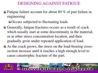
DESIGNING AGAINST FATIGUE. Fatigue failure account for about 80 % of part failure in engineering Occurs subjected to fluctuating loads

DESIGNING AGAINST FATIGUE
E N D
Presentation Transcript
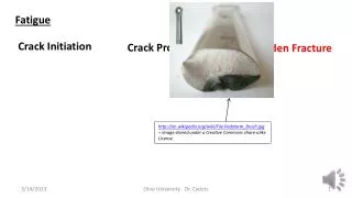
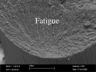
DESIGNING AGAINST FATIGUE • Fatigue failure account for about 80 % of part failure in engineering • Occurs subjected to fluctuating loads • Generally, fatigue fractures occurs as a result of crack which usually start at some discontinuity in the material, or at other stress concentration location, and then gradually grow under repeated application of load. • As the crack grows, the stress on the load-bearing cross-section increase until it reaches a high enough level to cause catastrophic fracture of the part.
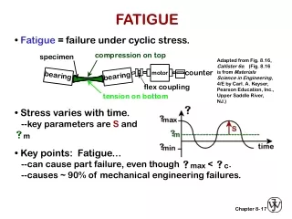
DESIGNING AGAINST FATIGUE • Fracture surface which usually exhibits smooth areas which correspond to the gradual crack growth stage, and rough areas, which correspond to the catastrophic fracture stage. • The smooth parts of the fracture surface usually exhibit beach marks which occurs as a result of changes in the magnitude of the fluctuating fatigue load. • Fatigue behavior of materials is usually described by means of the S-N diagram which gives the number of cycles to failure, N as a function of the max applied alternating stress, Sa.
DESIGNING AGAINST FATIGUE • Types of fatigue loading • Alternating stress • Alternating tension – compression • Stress ratio, R = min / max = -1 • Fluctuating stress • Positive R value • Greater tensile stress than compressive stress • max = m + a • max = m - a
DESIGNING AGAINST FATIGUE • Many types of test are used to determine the fatigue life of material • Small scale fatigue test – rotating beam test • Which a specimen subjected to alternating compression and tension stresses of equal magnitude while being rotate • Data from this result are plotted in the form of S-N curves • Which the stress S to cause failure is plotted against number of cycles N • Figure (a) – S-N curves for carbon steel (b) - S-N curves aluminum alloy
DESIGNING AGAINST FATIGUE • In the majority cases, the reported fatigue strength or endurance limits of the materials are based on the test of carefully prepared small samples under laboratory condition. • Such values cannot be directly used for design purposes because the behavior of a component or structure under fatigue loading does depend not only on the fatigue or endurance limit of the material used in making it, but also an several other factors including : • Size and shape of the component or structure • Type of loading and state of stress • Stress concentration • Surface finish • Operating temperature • Service environment • Method of fabrication
DESIGNING AGAINST FATIGUE • Endurance-limit modifying factors Se = kakbkckdkekfkgkhSe’ Where Se = endurance limit of component Se’ = endurance limit experimental ka = surface finish factor (machined parts have different finish) kb = size factor (larger parts greater probability of finding defects) kc = reliability / statistical scatter factor (accounts for random variation) kd = operating T factor (accounts for diff. in working T & room T) ke = loading factor (differences in loading types) kf = stress concentration factor kg = service environment factor (action of hostile environment) kh = manufacturing processes factor (influence of fabrication parameters)
ka = Surface finish factor • The surface finish factor, ka, is introduced to account for the fact that most machine elements and structures are not manufactured with the same high-quality finish that is normally given tolaboratory fatigue test specimens. DESIGNING AGAINST FATIGUE
DESIGNING AGAINST FATIGUE • kb = Size factor • Large engineering parts have lower fatigue strength than smaller test specimen • Greater is the probability of finding metallurgical flaws that can cause crack initiation • Following values can be taken as rough guidelines : • kb = 1.0 for component diameters less than 10 mm • kb = 0.9 for diameters in the range 10 to 50 mm • kb = 1 – [( D – 0.03)/15], where D is diameter expressed in inches, for sizes 50 to 225 mm.
DESIGNING AGAINST FATIGUE • kc = Reliability factor • Accounts for random variation in fatigue strength. • Published data on endurance limit, represent 50 % survival fatigue test. • Since most design require higher reliability, the published data must be reduced by the factor of kc • The following value can be taken as guidelines • kc = 0.900 for 90% reliability • kc = 0.814 for 99 % reliability • kc = 0.752 for 99.9 % reliability
DESIGNING AGAINST FATIGUE • kd = Operating temperature factor • Accounts for the difference between the test temperature and operating temperature of the component • For carbon and alloy steels, fatigue strength not affected by operating temperature – 45 to 4500C kd = 1 • At higher operating temperature • kd = 1 – 5800( T – 450 ) for T between 450 and 550oC, or • kd = 1 – 3200( T – 840 ) for T between 840 and 1020oF
DESIGNING AGAINST FATIGUE • ke = Loading factor • Accounts for the difference in loading between lab. test and service. • During service – vibration, transient overload, shock • From experience show that repeated overstressing can reduce the fatigue life • Different type of loading, give different stress distribution • ke = 1 for application involving bending • ke = 0.9 for axial loading • ke = 0.58 for torsional loading
DESIGNING AGAINST FATIGUE • kf = Stress concentration factor • Accounts for the stress concentration which may arise when change in cross-section • kf = endurance limit of notch-free part • endurance limit of notched part • Low strength, ductile steels are less sensitive to notched than high-strength steels
DESIGNING AGAINST FATIGUE • kg = Service environment factor • Accounts for the reduced fatigue strength due to the action of a hostile environment.
DESIGNING AGAINST FATIGUE • kh = Manufacturing process factor • Accounts for the influence of fabrication parameter • Heat treatment, cold working, residual stresses and protective coating on the fatigue material. • kh difficult to quantify, but important to included.
DESIGNING AGAINST FATIGUE • Endurance limit/Fatigue strength • The endurance limit, or fatigue strength, of a given material can usually be related to its tensile strength, as shown in table 2.2. • The endurance ratio, defined as (endurance limit/ tensile strength), can be used to predict fatigue behavior in the absence of endurance limits results. • From the table shows, endurance ratio of most ferrous alloys varies between 0.4 and 0.6
DESIGNING AGAINST FATIGUE • Other fatigue-design criteria • Safe-life or finite-life • Design is based on the assumption that the component is free from flaws, but stress level in certain areas is higher than the endurance limit of the material • Means that fatigue-crack initiation is inevitable and the life of the component is estimated on the number of stress cycles which are necessary to initiate crack
DESIGNING AGAINST FATIGUE • Fail-safe design • Crack that form in service will be detected and repaired before they can lead to failure. • Employed material adapted with high fracture toughness, crack stopping features and reliable NDT program to detect crack. • Damage-tolerant design • Is an extension of fail-safe criteria and assume that flaws exist in the component before they put in service. • Fracture mechanics techniques are used to determine whether such crack will grow large enough to cause failure before they are detected during periodic inspection.
DESIGNING AGAINST FATIGUE • Selection of materials for fatigue resistance • In many application, the behavior of a component in service is influence by several other factor besides the properties of the material used in its manufacture. • This is particularly true for the cases where the component or structure is subjected to fatigue loading. • The fatigue resistance can be greatly influenced by the service environment, surface condition of the part, method of fabrication and design details. • In some cases, the role of the material in achieving satisfactory fatigue life is secondary to the above parameters, as long as the material is free from major flaws
DESIGNING AGAINST FATIGUE • Steel and cast iron • Steel are widely used as structural materials for fatigue application as they offer high fatigue strength and good processability at relatively low cost. • The optimum steel structure for fatigue is tempered martensite, since it provide max homogeneity • Steel with high hardenability give high strength with relatively mild quenching and hence, low residual stresses, which is desire in fatigue applications. • Normalized structure, with their finer structure give better fatigue resistance than coarse pearlite structure obtained by annealing.
DESIGNING AGAINST FATIGUE • Nonferrous alloys • Unlike ferrous alloy, the nonferrous alloys, with the exception of titanium, do not normally have endurance limit. • Aluminum alloys usually combine corrosion resistance, light weight, and reasonable fatigue resistance • Fine grained inclusion-free alloys are most suited for fatigue applications.
DESIGNING AGAINST FATIGUE • Plastics • The viscoelasticity of plastics makes their fatigue behavior more complex than that of metals. • Fatigue behavior of plastics is affected by the type of loading, small changes in temperature and environment and method of fabrication • Because of their low thermal conductivity, hysteretic heating can build up in plastics causing them to fail in thermal fatigue or to function at reduces stiffness level. • The amount of heat generated increases with increasing stress and test frequency. • This means that failure of plastics in fatigue may not necessarily mean fracture
DESIGNING AGAINST FATIGUE • Composite materials • The failure modes of reinforced materials in fatigue are complex and can be affected by the fabrication process when difference in shrinkage between fibers and matrix induce internal stresses. • However from practical experiences, some fiber reinforced plastics are known to perform better in fatigue than some metal, refer table 2.2. • The advantage of fiber-reinforced plastics is even more apparent when compared on a per weight basics. • As with static strength, fiber orientation affects the fatigue strength of fiber reinforced composite
DESIGNING AGAINST FATIGUE • In unidirectional composites, the fatigue strength is significantly lower in directions other than the fiber orientation. • Reinforcing with continuous unidirectional fibers is more effective than reinforcing with short random fibers.