Xilinx Tool Flow
Xilinx Tool Flow. Objectives. After completing this module, you will be able to: List the steps of the Xilinx design process Implement and simulate an FPGA design by using default software options . Outline. Overview ISE Foundation Summary Lab 1: Xilinx Tool Flow Demo. Xilinx Design Flow.


Xilinx Tool Flow
E N D
Presentation Transcript
Xilinx Tool Flow This material exempt per Department of Commerce license exception TSU
Objectives After completing this module, you will be able to: • List the steps of the Xilinx design process • Implement and simulate an FPGA design by using default software options
Outline • Overview • ISE Foundation • Summary • Lab 1: Xilinx Tool Flow Demo
Xilinx Design Flow Create Code/ Schematic HDL RTL Simulation Plan & Budget Implement Functional Simulation Synthesize to create netlist Translate Map Place & Route Timing Simulation GenerateBIT File Attain Timing Closure ConfigureFPGA
Design Entry Create designs in HDL or Schematic • Plan and budget • Whichever method you use, you will need a tool to generate an EDIF or NGC netlist to bring into the Xilinx implementation tools • Popular synthesis tools include: Synplify, Precision, FPGA Compiler II, and XST • Tools available to assist in design entry • Architecture Wizard, CORE Generator™ system, and StateCAD tools • Simulate the design to ensure that it works as expected! Plan & Budget Create Code/ Schematic HDL RTL Simulation Functional Simulation Synthesize to create netlist . . .
Synthesis Generate a netlist file • After coding up your HDL code, you will need a tool to generate a netlist (NGC or EDIF) • Xilinx Synthesis Tool (XST) included • Support for Popular Third Party Synthesis tools: Synplify and Synplify Pro from Synplicity, and Precision from Mentor Graphics
Implementation Process a netlist file • Consists of three phases • Translate: Merge multiple design files into a single netlist • Map: Group logical symbols from the netlist (gates) into physical components (slices and IOBs) • Place & Route: Place components onto the chip, connect the components, and extract timing data into reports • Access Xilinx reports and tools at each phase • Timing Analyzer, Floorplanner, FPGA Editor, XPower Netlist GeneratedFrom Synthesis . . . Implement . . . Translate Map Place & Route . . .
Configuration Testing and Verification • Once a design is implemented, you must create a file that the FPGA can understand • This file is called a bitstream: a BIT file (.bit extension) • The BIT file can be downloaded • Directly into the FPGA • Use a download cable such as Platform USB • To external memory device such as a Xilinx Platform Flash PROM • Must first be converted into a PROM file
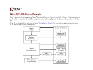
Online Software Manuals See Development System Reference Guide for Flow Diagrams
Outline • Overview • ISE Foundation • Summary • Lab 1: Xilinx Tool Flow Demo
ISE Project Navigator Xilinx ISE Foundation is built around the Xilinx Design Flow • Enter Designs • Access to synthesis tools • Including third-party synthesis tools • Implement your design with a simple double-click • Fine-tune with easy-to-access software options • Download • Generate a bitstream • Configure FPGA using iMPACT
Entering Designs Source Wizard available to assist with design entry • Select source type • Design Entry Methods • Schematic • HDL source (VHDL andVerilog) • Design Entry Tools • Architecture Wizard • BMM/MEM/UCF Files • Core Generator • ChipScope • Embedded Processor • System Generator • Simulation Test Bench • VHDL • Verilog
Synthesizing Designs Generate a netlist file using XST (Xilinx Synthesis Technology) • Synthesis Processes and Analysis • Access report • View Schematics (RTL or Technology) • Check Syntax • Generate Post-Synthesis Simulation Model 1 Highlight HDLSources 2 Double-click to Synthesize
Implementing Designs Process netlist generated from synthesis • Implement a design • Translate • Access reports • Post-Translate Simulation Model • Map • Access reports • Post-Map Static Timing • Manually place components • Post-Map Simulation Model • Place & Route • Access reports • Analyze timing/Floorplan (PlanAhead) • Manually place & route components • And more 1 Highlight HDLSources 2 Double-click to Implement
The Design Summary Displays Design Data • Quick View of Reports, Constraints • Project Status • Device Utilization • Detailed Reports • Design Properties • Performance Summary (not shown)
Simulating Designs Verify the design with the ISE Simulator 1 2 • Add a test bench • VHDL, Verilog, or Xilinx waveform file • Perform a Behavioral Simulation • Use UNISIM/UniMacro library when FPGA primitives are instantiated in the design • Use XilinxCoreLib library when IP cores are instantiated in the design • Perform a timing simulation • Use Xilinx SIMPRIM library when FPGA primitives are instantiated in the design • SmartModels • Simulation library for both functional and timing simulation of Xilinx Hard-IP such as PPC, PCIe, GT, TEMAC are used in the design Select simulation Select simulation type 3 Highlight test bench 4 Double-click tosimulate
Configuring FPGAs Generate PROM files and download to devices using iMPACT • Configure FPGAs from computer • Use iMPACT to download bitstream from computer to FPGA via Xilinx download cable (ie. Platform USB) • Configure FPGAs from External Memory • Xilinx Platform Flash • Use iMPACT to generate PROM file and download to PROM using Xilinx download cable • Generic Parallel PROM • Use iMPACT to generate PROM file - no support for programming • Compact Flash (Xilinx System ACE required) • Use iMPACT to generate SysACE file - no support for programming 1 Highlight source file 2 Double-click to generate .bit 3 Double-click to invoke iMPACT programming tools
Outline • Overview • ISE • Summary • Lab 1: Xilinx Tool Flow
Review Questions • What are the phases of the Xilinx design flow? • What are the components of implementation, and what happens at each step? • What are two methods of programming an FPGA?
Answers • What are the phases of the Xilinx design flow? • Plan and budget, create code or schematic, RTL simulation, synthesize, functional simulation, implement, timing closure, timing simulation, and BIT file creation • What are the components of implementation, and what happens at each step? • Translate: merges multiple design files into one netlist • Map: groups logical symbols into physical components • Place & Route: places components onto the chip and connects them • What are two methods of programming an FPGA? • Directly from Computer • From external memory device
Summary • Implementation means more than Place & Route • Xilinx provides a simple pushbutton tool to guide you through the Xilinx design process
Outline • Overview • ISE • Summary • Lab 1: Xilinx Tool Flow