RF Power Equipment for Crab Cavity Tests at SPS
130 likes | 149 Vues
Explore the development and setup of RF power equipment for testing new crab cavities at SPS, including drivers, peripherals, interfaces, and system configurations. Learn about past amplifier tests, power transmission methods, and future planning for SPS 352 MHz systems.

RF Power Equipment for Crab Cavity Tests at SPS
E N D
Presentation Transcript
Crab CavityRF Power … for SPS tests E. Montesinos presented by E. Jensen
Contents • Basic illustration • Finals • Drivers • Peripherals • FPC
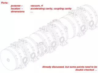
Basic illustration • For the tests we foresee in the SPS, RF power equipment for a new crab cavity are: • Driver • Flexwell cable • Final • Waveguide • Fundamental Power Coupler (FPC) • Two complete systems are to be built in the SPS: Waveguides Flexwell cable Final Driver FPC Cryo module LLRF
Finals • During the LEP era, four 352 MHz SC Cavities were in operation in the SPS. • Custom-designed tetrode amplifiers were developed at CERN to feed these cavities. • In 1998, a prototype 400 MHz LHC cavity has been tested in the SPS. • It was powered with one of these 352 MHz amplifiers, modified to operate at 400 MHz. • Maximum output power was 40 kW CW. • The main idea is to re-use this amplifier and to modify two additional ones (from the four SPS ones) to feed two new Crab Cavities and have one spare. SPS 352 MHz Tetrode Amplifier
Finals Location • RF transmission line between Finals and Fundamental Power Couplers (FPC) were WG. • Due to power levels, as there is not a lot of free space in the SPS tunnel, we plan to re-use a very similar configuration: • Finals very close to the cavities, • Waveguide Transmission lines between Finals and FPC. • An alternative solution can be with coaxial cables (following slides) FPC WG Transmission Line Cryomodule Final Tetrode Amplifier SPS 352 MHz SCC during the 90s
Finals Peripherals • Anode HV power supplies cannot sit in the same tunnel area. • Two options are looked at: • BA4 surface building, • ECX4 underground cavern. • Choice will mainly be driven by free cable trays and infrastructure availability: • old SPS equipment has been dismantled, • Areas have been re-used for other new projects, • All has to be rebuilt It is not yet known if HVPS can be re-used or if new ones will have to be purchased. Four HVPS for SPS 352 MHztetrode amplifiers
Drivers 0 dBm From LLRF To Final • Tetrode Finals have a gain of 13 dB.To provide 60 kW, a 3 kW driver will be needed. • In the past, a driver was chain of : • 1 W SSA, • 100 W SSA, • 3 kW Tetrode amplifier. • A new 0 dBm to 500 W CW SSA prototype has been ordered. 1W SSA 100W SSA 3 kW Tetrode SPS 352 MHz Drivers during the 90s
Drivers • Two options for the new driver chains are under study: • 500 W SSA + re-use of the 3 kW tetrodeamplifier • Main advantage: Tetrode amplifier already exists, • Main drawback: HVPS! • 6 x 500 W drivers combined (preferred solution) • Main advantages: NO HVPS and less foot print (1 rack) • Main drawback: more space needed outside tunnel (non radioactive area). 0dBm From LLRF To Final 3 kW Tetrode 500W SSA Option with 500 W SSA + 3 kW Tetrode 0 dBm From LLRF To Final 6 x 500W SSA Option with 6 x 500 W SSA
Other Peripherals • Other peripherals will have to sit close to the Finals such as: • Air blower, • HV Filtering Box (due to the distance between Finals and their HVPS). • All other ancillaries will be located close to the HVPS: • Filament and Grids Power Supplies, • Finals controls. • A new demineralized water cooling system will also have to be built as amplifiers are water cooled. Air blower and HV filtering box close to the tetrode amplifier Demineralized water plant
Alternative RF power location option • An alternative option would be to have all RF power chain on a surface building (BA4 or ECX4), close to the LLRF. • As power level remained below 60 kW, we could feed the cavity through a power coaxial Flexwell. • Available space in the pit has to be checked. • This was the ex-SWC100MHz solution already done at (nearly) the same location in the SPS. High power Flexwell cable coming from the BA4 surface building and directly connected to FPC New Crab Cavities area SPS 100 MHz SCC during the 90s
FPC (Fundamental Power Coupler) • Simulations have not yet started • New couplers will be designed taking into account past and recent experiences with FPC, such as : Linac 4 352 MHz coupler LHC 400 MHz coupler SPL 704 MHz couplers ANL-APS coupler ESRF 352 MHz coupler
Thank you for your attention More to come at the December Fermilab Crab Cavity Engineering meeting…