MP Electronics, Basic Concept
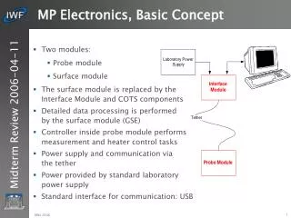
MP Electronics, Basic Concept. Two modules: Probe module Surface module The surface module is replaced by the Interface Module and COTS components Detailed data processing is performed by the surface module (GSE) Controller inside probe module performs measurement and heater control tasks

MP Electronics, Basic Concept
E N D
Presentation Transcript
MP Electronics, Basic Concept • Two modules: • Probe module • Surface module • The surface module is replaced by the Interface Module and COTS components • Detailed data processing is performed by the surface module (GSE) • Controller inside probe module performs measurement and heater control tasks • Power supply and communication via the tether • Power provided by standard laboratory power supply • Standard interface for communication: USB MBS 2006
MP Electronics Module (1) • Dedicated electronics department inside the probe • Cylindrical tube with top and bottom cover • Three braces at 120° position provide the fixation of the PCB's • Braces are used to fix the electronics compartment inside the probe • Fixed connector at top cover provides the interface to the tether • Pig-tails (TBC) located at the bottom cover provide the interface to the heaters and sensors MBS 2006
MP Electronics Module (2) • Power conditioner • Controller • Communication • Signal conditioning • Heater Control MBS 2006
MP Electronics Module (3) • Circuit diagrams not fully completed • Electronics will be spread to 5...6 PCB's (55mm diameter) • Connection to tether and external heaters and sensors via MDM connector • PCB interconnection via spring contacts and gold plated pads MBS 2006
Power Conditioner • Supply via the tether with 28V (laboratory power supply) • Use of two redundant pairs (AWG ?) • High power Schottky diodes at +28V input • Heaters directly supplied from 28V • DC/DC converter 28V / 5V to supply electronics • Linear regulator to generate supply voltage for Ph sensor MBS 2006
Controller • Prototype is based on PIC18F4550 • Frequency: up to 40MHz, inbuilt 8MHz clock • Program memory: 32KByte • Data memory: 16kByte • ADC: 10 bit, 13 channels, 5V range • On-chip USB interface • 44-pin TQFP plastic package • Operational temperature range: -40°C...+85°C • Storage temperature range: -65°C...+150°C • Wide supply voltage range MBS 2006
Communication • The communication channel uses the same signal lines as the power supply • Binary frequency shift key modulation for signal transmission will be used • Use of two carrier frequencies to support full-duplex mode • The communication will be based on the USB protocol • Frequencies not yet selected • Detailed design not yet finished MBS 2006
Heater Control • Large variation of impedance due to environmental condition • Individual current limiter for each heating segment • Power management to minimize EMC radiation and losses • Heating segments switched sequentially • Concept for power sharing in low power mode under investigation • Control loop activated every 10ms (TBC) • Dedicated bang-bang controller with adjustable nominal temperature for each segment • Highest priority is given to front segment, while rear segment has lowest priority • Electronics calculates duty-cycle for each heater segment MBS 2006
Temperature Measurement • Measurement shall support a temperature range between -200°C and +100°C • Five Pt100 are dedicated to the heater segments, four additional sensors are available for individual measurements • Pt100's are supplied with constant current of 1mA • Four wire interface is important since impedance of Pt100 varies from approx. 20Ω to 140Ω • Common GND line to save connector pins (three wire interface) • Resolution approx. 0.5°C/digit MBS 2006
Analogue & Digital Measurements MBS 2006
Communication Protocol • Data are sent only on request • A response is send for each command, either simple ACK/NACK or data-set • Commands: • Set the nominal value for the control loop • Requests the temperature values • Requests all measurement values • Requests the nominal temperatures for the control loops • Request duty cycle MBS 2006
Data-Set • Acknowledge / Not acknowledgeNACK will include simple failure code • Temperature dataThe temperature value for all five heater segments • All measurement dataA complete of measured data, temperatures, tilt angles and Ph value • Nominal temperature valuesRead-back of the reference values for the heater control loops • Duty cycleActive time of a heater during 1sec time periodResolution 1% (TBC) MBS 2006
Software Design • Design based on Ward-Mellor method • Implementation with the MPE Lab IDE • Coding in C based on the Microchip C18 compiler • USB driver provided by Microchip • Measurement of analogue signals (Pt100 & Ph) by use of inbuilt ADC • Measurement of digital signals (tilt sensor) by use of capture/compare registers MBS 2006
Software Interfaces MBS 2006
Software, Decomposition Level 0 MBS 2006