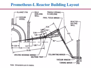
Prometheus-L Reactor Building Layout
220 likes | 267 Vues
Prometheus-L Reactor Building Layout. Two Main Options for the Final Optic. (1) SiO 2 or CaF 2 wedges. (2) Grazing incidence metal mirror. Neutrons and g -rays create defects in SiO 2 which result in photon absorption. MeV n 0. Normal Site. Si. Si. O.

Prometheus-L Reactor Building Layout
E N D
Presentation Transcript
Two Main Options for the Final Optic (1) SiO2 or CaF2 wedges (2) Grazing incidence metal mirror
Neutrons and g-rays create defects in SiO2 which result in photon absorption MeV n0 Normal Site Si Si O Oxygen Deficient Center (ODC, 246 nm) Non-Bridging Oxygen Hole Center (NBOHC, 620 nm) + Si Si Si Si O- O- O2- annealing MeV g-rays annealing Si+ Si Si Si O E’ Center (213 nm) Normal Site
Final Optic Damage Threats Final Optic Threat Nominal Goal Optical damage by laser >5 J/cm2 threshold (normal to beam) Sputtering by ions Wavefront distortion of <l/3 * (~100 nm) Ablation by x-rays (6x10⁸ pulses in 2 FPY: (~25 mJ/cm2, partly stopped by gas) 2.5x10⁶ pulses/allowed atom layer removed) Defects and swelling induced by Absorption loss of <1% g-rays (~3) and neutrons (~18 krad/s) Wavefront distortion of < l/3 * Contamination from condensable Absorption loss of <1% materials (aerosol and dust) >5 J/cm2 threshold Two main concerns: • Damage that increases absorption (<5%) • Damage that modifies the wavefront – • spot size/position (200mm/20mm) and spatial uniformity (1%) *“There is no standard theoretical approach for combining random wavefront distortions of individual optics. Each l/3 of wavefront distortion translates into roughly a doubling of the minimum spot size.” (Ref. Orth)
MeV g / n° irradiation of CaF2 at room temperature also leads to the formation of color centers 1 Mrad g-rays (60Co), post-annealing 766 kRad n˚ Absorption Coefficient (cm-1) Annealed at 385˚C (Goal ~0.01/cm) • 10 MRad g-irradiation (60Co) yields no color centers for virgin sample • Absorptions at 335, 410, and 540 nm due to color centers • Color center is a “missing fluorine” that captures an electron • Annealing removes absorption due to n0 induced color centers • CaF2 is “softened” by n0 (g-irradiation induces color center of annealed sample)
GIMM development issues* Experimental verification of laser damage thresholds Protection against debris and x-rays (shutters, gas jets, etc.) Wavefront issues: beam smoothness, uniformity, shaping, f/number constraints Experiments with irradiated mirrors In-situ cleaning techniques Large-scale manufacturing Cooling * from Bieri and Guinan, Fusion Tech. 19 (May 1991) 673.
Shallow angle reflectivity measurements of undamaged surfaces
Surface deformation leads to roughening and loss of laser beam quality • Single Shot Effects on LIDT: • Laser heating generates point defects • Coupling between diffusion and elastic fields lead to permanent deformation • Progressive Damage in Multiple Shots: • Thermoelastic stress cycles shear atomic planes relative to one another (slip by dislocations) • Extrusions & intrusions are formed when dislocations emerge to the surface, or by grain boundary sliding. • F1 varies from a few to ~ 10 J/cm2. • LIDT is a strong function of material & number of shots – it degrades up to a factor of 10 after only 10000 shots (survival to ~108 shots is needed). • Uncertainty in saturation behavior
Laser Damage Experiments to Metal Mirrors Spectra Physics YAG laser: 2J, 10 ns @1064 nm; 800, 500, 300 mJ @532, 355, 266 nm Peak power density ~1014 W/cm2
Several kinds of Al surfaceshave been fabricated and characterized 75 nm Al on superpolished flat: ±2Å roughness, 10Å flatness diamond-turned Al 6061 Al 1100 showing grain boundaries and tool marks MgSi occlusions
Surface deformation patterns after one laser shot of intensity near LIDT (Solution of continuum equations with defect diffusion in the self-consistent elastic field) Focused Laser-induced Surface Deformation (vacancy density correlates with deformation) Uniform Laser-induced Surface Deformation Computer Simulation Computer Simulation Experiment (The model correctly predicts number of arms) (Walgraef, Ghoniem & Lauzeral, Phys. Rev. B, 56, 23, (1997) 1536) Focused laser-induced surface deformation (Lauzeral, Walgraef & Ghoniem,Phys. Rev. Lett. 79, 14 (1997) 2706)
Progressive damage in multiple shots is caused by successive dislocation slip & grain boundary sliding Low Density High Density
A reflectometer accurately measures reflectivity 100 ppm accuracy
Damage to aluminum at grazing angles Several shots in Al 6061 at 80˚, 1 J/cm2 1000 shots in Al 1100 at 85˚, 1 J/cm2 MgSi Fe Fe 1000x 1000x Silicide occlusions in Al 6061 preferen-tially absorb light, causing explosive ejection and melting at only 1 J/cm2; Fe impurities appear unaffected Exposure of Al 1100 to 1000 shots at 85˚ exhibited no damage up to 18 J/cm2
For more information…. http://aries.ucsd.edu/IFE http://lasers.llnl.gov/lst/advanced.html http://puma.seas.ucla.edu/web_pages
Damage to aluminum at grazing angles Single pulse in pure Al at 85˚, 180 J/cm2 10000 shots in Al 1100 at 85˚, 20 J/cm2 Exposure of Al 1100 to 10000 shots at 85˚ exhibits catastrophic damage at fluence >20 J/cm2 99.999% pure Al survives single shot damage up to the melting limit