Download
1 / 29
290 likes | 522 Vues
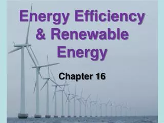
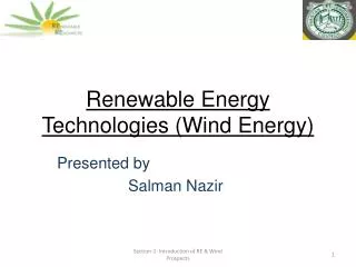
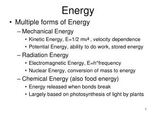
Wind Energy: State-of-the Art and Future Trends Southwest Renewable Energy Conference. James F. Manwell, Ph.D., Director Univ. of Mass. Renewable Energy Research Laboratory August 8, 2003. Recent History Wind Turbines Today Economics and Wind Energy Development Future Trends. Overview.

E N D
Wind Energy:State-of-the Art and FutureTrendsSouthwest Renewable Energy Conference James F. Manwell, Ph.D., Director Univ. of Mass. Renewable Energy Research Laboratory August 8, 2003
Recent History Wind Turbines Today Economics and Wind Energy Development Future Trends Overview
Historically Important Small Wind Turbines Jacob’s Wind Generator, 1930’s Traditional Water Pumping Windmill
Historically Important Large Wind Turbines Smith-Putnam, VT, 1940’s Gedser, Denmark, 1950’s
Modern Wind Turbine Hull, MA 2003
Wind Farm Palm Springs, CA, 2001 Utility Grid with Wind Farm
Axis orientation: Horizontal/Vertical Power control: Stall/Variable Pitch/Controllable Aerodynamic Surfaces/Yaw Control Yaw Orientation: Driven Yaw/Free Yaw/Fixed Yaw Rotor Position: Upwind of Tower/Downwind of Tower Type of Hub: Rigid/Teetered/Hinged blades/Gimbaled Design Tip Speed Ratio Solidity (Relative Blade Area) Number of Blades: One, Two, Three Rotor Speed: Constant/Variable Wind Turbine Topology Options
Rotor Drive Train Yaw System Main Frame Tower Control System Wind Turbine Subsystems and Components Skip details
Hub connects the blades to the main shaft Usually made of steel Types Rigid Teetered Hinged Rotor: Hub Hub of 2 Blade Turbine
Blades Some Planform Options
Main Shaft is principal rotating element, transfers torque from the rotor to the rest of the drive train. Usually supports weight of hub Made of steel Drive Train: Main Shaft
Generator Converts mechanical power to electricity Couplings Used to Connect Shafts, e.g. Gearbox High Speed Shaft to Generator Shaft Drive Train
Gearbox increases the speed of generator input shaft Main components: Case, Gears, Bearings Types: i) Parallel Shaft, ii) Planetary Drive Train: Gearbox Typical Planetary Gearbox (exploded view)
Mechanical Brake used to stop (or park) rotor Usually redundant with aerodynamic brakes Types: Disc Clutch Location: Main Shaft High Speed Shaft Design considerations: Maximum torque Length of time required to apply Energy absorption Drive Train: Mechanical Brake Disc Brake
The Yaw System orients the turbine to the wind Types Active Yaw (Upwind turbines) Employs motor and gearing May Need Yaw Brake to Prevent Excess Motion Free Yaw (Downwind turbines) Relies on wind forces for alignment May Need Yaw Damper or Power Cable "Unwinder" Yaw System Yaw Drive
The Main Frame is the platform to which the other principal components are attached. Provides for proper alignment among those components Provides for yaw bearing and ultimately tower top attachment Usually made of cast or welded steel Main Frame
The nacelle cover is the wind turbine housing Protects turbine components from weather Reduces emitted mechanical sound Often made of fiberglass Nacelle Cover
Raises turbine into the air Ensures blade clearance Types Free standing lattice (truss) Cantilevered pipe (tubular tower) Guyed lattice or pole. Tower Installation of Tubular Tower
Experience California, Europe Computers (intelligence) Design, monitoring, analysis, control Materials Composites Design standards Specification of conditions Ensure safety & reliability Success of Modern Turbines
Cost of energy (COE), $/kWh COE = (C*FCR+O&M)/E Depends on: Installed costs, C Fixed charge rate, FCR – fraction of installed costs paid each year (including financing) O & M (operation & maintenance) Annual energy production, E Cost of Energy
Wind Size range: 500 W- 2,000 kW Installed system: $900-1500/kW COE: $0.04 – 0.15/kWh Typical Costs
Use ‘Capacity Factor’ (CF) CF = Actual Energy/Maximum Energy E = CF x Rated Power x 8760 (kWh/yr) Typical Range: CF = 0.15 - 0.45 CF ideally > 0.25 Typical Energy Production
Rotor: ~85% of theoretical Gearbox: ~97% Generator: ~95% Power electronics: ~92-95% Efficiencies
Installation, maintenance of very large turbines Transmission from windy areas to load centers Fuel production (hydrogen by electrolysis) Public acceptance Challenges
Example: Transportation Challenges Is this the way to move large turbines?
Larger turbines Improvements in design details More sophistication Example: self-diagnosis and correction Improved power electronics Effective use of high wind ites Great plains Offshore Designs for lower wind sites Future
Focus on complete system Transmission High value applications Energy storage Fuel creation (hydrogen) Wind+Turbine -> Electricity Electricity + Water -> H2 (+O2) Future (2)