16.360 Lecture 7
140 likes | 158 Vues
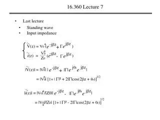
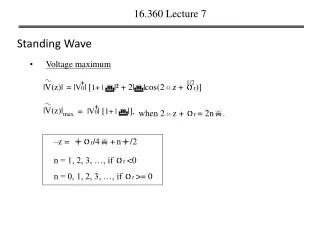
+. |V(z)|. | V 0 | [ 1+ | | ],. =. max. |V(z)|. +. 1/2. = | V 0 | [ 1+ | | ² + 2| |cos(2 z + r )]. 16.360 Lecture 7. Standing Wave. Voltage maximum. when 2 z + r = 2n. –z = r /4 + n/2. n = 1, 2, 3, …, if r <0. n = 0, 1, 2, 3, …, if r >= 0. +.

16.360 Lecture 7
E N D
Presentation Transcript
+ |V(z)| |V0| [1+ | |], = max |V(z)| + 1/2 = |V0| [1+ | |² + 2||cos(2z + r)] 16.360 Lecture 7 Standing Wave • Voltage maximum when 2z + r = 2n. –z = r/4+n/2 n = 1, 2, 3, …, if r <0 n = 0, 1, 2, 3, …, if r >= 0
+ |V(z)| |V0| [1 - | |], = min |V(z)| + 1/2 = |V0| [1+ | |² + 2||cos(2z + r)] 16.360 Lecture 7 • Voltage minimum when 2z + r = (2n+1). –z = r/4+n/2 + /4 Note: voltage minimums occur /4 away from voltage maximum, because of the 2z, the special frequency doubled.
S |V(z)| |V(z)| min max 1 + | | = 1 - | | 16.360 Lecture 7 • Voltage standing-wave ratio VSWR or SWR S = 1, when = 0, S = , when || = 1,
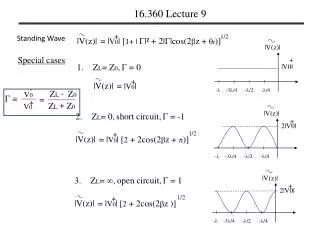
|V(z)| + V0 + |V0| - -3/4 -/2 -/4 |V(z)| + - 2|V0| V0 |V(z)| |V(z)| + 2|V0| - -3/4 -/2 -/4 + 1/2 - -3/4 -/2 -/4 = |V0| [1+ | |² + 2||cos(2z + r)] 16.360 Lecture 7 Standing Wave Special cases • ZL= Z0, = 0 + |V(z)| = |V0| - ZL Z0 = + ZL Z0 2. ZL= 0,short circuit, = -1 + 1/2 |V(z)| = |V0| [2 + 2cos(2z + )] 3. ZL= ,open circuit, = 1 + 1/2 |V(z)| = |V0| [2 + 2cos(2z )]
+ V0 Z0 jz jz -jz -jz e (e e (e 16.360 Lecture 7 short circuit line B Ii A Zg Vg(t) sc Z0 VL Zin ZL = 0 l z = - l z = 0 ZL= 0, = -1, S = + V(z) = V0 ) - = -2jV0sin(z) + + i(z) = ) = 2V0cos(z)/Z0 V(-l) Zin = jZ0tan(l) = i(-l)
-1 l = 1/[- tan (1/CeqZ0)], 16.360 Lecture 7 short circuit line V(-l) Zin = jZ0tan(l) = i(-l) • If tan(l) >= 0, the line appears inductive, jLeq= jZ0tan(l), • If tan(l) <= 0, the line appears capacitive, 1/jCeq= jZ0tan(l), • The minimum length results in transmission line as a capacitor:
-1 l = 1/[- tan (1/CeqZ0)], 16.360 Lecture 7 An example: Choose the length of a shorted 50- lossless line such that its input impedance at 2.25 GHz is equivalent to the reactance of a capacitor with capacitance Ceq = 4pF. The wave phase velocity on the line is 0.75c. Solution: Vp= ƒ, = 2/ = 2ƒ/Vp = 62.8 (rad/m) tan (l)= - 1/CeqZ0 = -0.354, -1 l= tan (-0.354) + n, = -0.34 + n,
+ = 2V0cos(z) + V0 Z0 jz jz -jz -jz e (e e (e 16.360 Lecture 7 open circuit line B Ii A Zg Vg(t) oc Z0 VL Zin ZL = l z = - l z = 0 ZL = , = 1, S = + V(z) = V0 ) + - i(z) = ) = 2jV0sin(z)/Z0 V(-l) oc Zin = -jZ0cot(l) = i(-l)
16.360 Lecture 7 Short-Circuit/Open-Circuit Method For a line of known length l, measurements of its input impedance, one when terminated in a short and another when terminated in an open, can be used to find its characteristic impedance Z0and electrical length
16.360 Lecture 7 Line of length l = n/2 tan(l) = tan((2/)(n/2)) = 0, Zin = ZL Any multiple of half-wavelength line doesn’t modify the load impedance.
(1 - ) Z0 (1 + ) -j2l -j2l e e - + (1 (1 ) ) Z0 16.360 Lecture 7 Quarter-wave transformer l = /4 + n/2 l = (2/)(/4 + n/2) = /2 , -j e + ) (1 Zin(-l) = = Z0 = -j e - (1 ) = Z0²/ZL
16.360 Lecture 7 An example: A 50- lossless tarnsmission is to be matched to a resistive load impedance with ZL = 100 via a quarter-wave section, thereby eliminating reflections along the feed line. Find the characteristic impedance of the quarter-wave tarnsformer. Z01 = 50 ZL = 100 /4 = Z0²/ZL Zin Zin = Z0²/ZL= 50 ½ ½ Z0 = (ZinZL) = (50*100)
16.360 Lecture 7 Matched transmission line: • ZL = Z0 • = 0 • All incident power is delivered to the load.