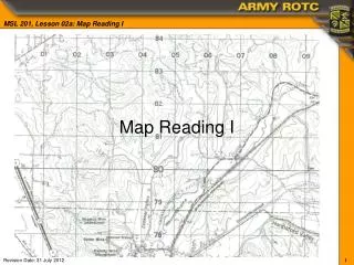
INTRODUCTION TO MAP READING
INTRODUCTION TO MAP READING. Outline . Purpose Marginal Information Colors Terrain Features Conclusion. Purpose. To lay the groundwork for successful map reading and land navigation by exposing the cadet to basic information, significant color coding, and terrain features used on maps.

INTRODUCTION TO MAP READING
E N D
Presentation Transcript
Outline • Purpose • Marginal Information • Colors • Terrain Features • Conclusion Map Reading I
Purpose To lay the groundwork for successful map reading and land navigation by exposing the cadet to basic information, significant color coding, and terrain features used on maps. Map Reading I
DEFINITION OF A MILITARY MAP A MAP IS A GEOGRAPHIC REPRESENTATION OF A PORTION OF THE EARTH’S SURFACE DRAWN TO SCALE, AS SEEN FROM ABOVE. MILITARY MAP IS ALSO CALLED A TOPOGRAPHIC MAP. IT’S USES COLORS, SYMBOLS ANDLABELSTO REPRESENT FEATURES FOUND ON THE GROUND.
Marginal Information (1) Tenino • Sheet Name • Sheet Number • Adjoining Map Sheets Diagram • Stock Number Edition 7-DMATC Series V791 Sheet 1477 IV
Marginal Information (2) • Declination Diagram • Special Notes
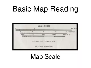
Marginal Information (3) • Scale • Bar Scales • Contour Interval Notes • Grid Reference Box
Marginal Information (4) • Map Agency • Legend
Highway Road Dirt Road Trail Buildings Built-up Areas Airports Bridge Landing Strip Gravel Pit School Foot Bridge Church Mine Cemetery cem Power Lines Railroad MAN-MADE FEATURES and HIGHWAYS
UTM GRID or GRID NORTH COORDINATES Below is the Universal Transverse Mercator (UTM) grid.
HERE IS A BETTER WAY OF LOOKING AT THE UTM GRID LAYOUT The world is divided into 60 zones. Here you can see ZONES 1 thru 60 at the top of the world map. 22 26 32 36 21 24 25 28 30 31 34 35 38 40 23 27 29 33 37 39 2 6 12 16 42 46 52 56 1 4 5 8 10 11 14 15 18 20 41 44 45 48 50 51 54 55 58 60 3 7 9 13 17 19 43 47 49 53 57 59 EQUATOR LINE
100,000-meter Square Identifiers
Grid Zone Identification • 4-Digit Coordinate: within 1000 meters • 6-Digit Coordinate: within 100 meters • 8-Digit Coordinate: within 10 meters *The more digits in a grid coordinate, the closer the location.
Colors (x6) • BLACK: Man-made features (Buildings, roads, grid-lines) • RED-BROWN:cultural features (contour lines) • BLUE: Water features (Lakes, swamps and rivers) • BROWN: Relief features and elevation on older or red-light readable maps (contour lines and cultivated land) • GREEN: Vegetation (forest, woods, brush, orchards) • RED: Man-made features (populated areas, major highway roads, boundaries on older maps) Map Reading I
1. Check contour interval 2. Find given elevation 3. Determine direction of slope 4. Count contour intervals. Contour Lines & Interval Change in ELEVATION Map Reading I
CONTOUR LINES A=700 ft B=740 ft C=770 ft D=820 ft Contour Interval ~ The contour interval is the distance between each contour line. The contour interval is found along the bottom edge, center of the map. Intermediate Contour ~ a brown line on a topographic map and represents a line of equal elevation. Index Contour ~ a bolder/wider brown line that has the elevation value marked at various intervals as a part of the line. Example: contour is 20 feet interval
Contour Lines & Interval Lines that are farther apart (interval) = GENTLE SLOPE Map Reading I
Contour Lines & Interval Lines that are close together (interval) = STEEP SLOPE Map Reading I
Major Terrain Features (x 5) Hill. Valley. Ridge. Saddle. Depression. H idden V alley R anch S alad D ressing Map Reading I
Major Terrain Features1 of 5 Hill: An area of high ground - Concentric circles. The center of the smallest circle is the hilltop. Map Reading I
V a l l e y Major Terrain Features3 of 5 Valley:a stretched‑out groove in the land, usually formed by streams or rivers. - U or V shaped contour lines. High ground on 3 sides usually with water flowing in the middle. V or U points upstream. Map Reading I
Major Terrain Features4 of 5 Ridge: This is a sloping line of high ground. - low ground in three directions and high ground in one direction. Contour lines tend to be U‑shaped or V‑shaped. The closed end of the contour line points to lower ground Map Reading I
Major Terrain Features2 of 5 Saddle: Low point between 2 areas of high ground - hour glass or figure eight contour lines. X Map Reading I
Major Terrain Features5 of 5 Depression: This is a low point in the ground. - Low ground or sink hole. Closed contour lines that have tick marks pointing toward low ground. Map Reading I
Minor Terrain Features (x 3) Draw. Spur. Cliff. Map Reading I
Minor Terrain Features1 of 3 Draw:a less developed stream course than a valley. There is essentially no level ground . • contour lines depicting a draw are U‑shaped or V‑shaped, • pointing toward high ground. Map Reading I
Minor Terrain Features2 of 3 Spur:a short, continuous sloping line of higher ground, normally jutting out from the side of a ridge. - Contour lines depict the U or V pointing away from high • ground. Map Reading I
Minor Terrain Features3 of 3 Cliff: a vertical or near vertical feature. • Contour line converge together into one “Carrying” contour. The last contour has tick marks pointing towards low ground. Sometimes depicted by contours running very close or touching. Map Reading I
Supplementary Terrain Features (x 2) Cut. Fill. Map Reading I
Supplementary Terrain Features Cut or Fill: a man‑made feature resulting from cutting through high ground or filling low ground. • Contour line extends the length of the cut (tick marks point to roadbed) and fill (tick marks point away from roadbed). Map Reading I
CUT FILL
Practical Exercise 8 9 6 6 Map Reading I
Practical Exercise Key Map Reading I
Summary • Purpose • Marginal Information • Colors (x6) • Terrain Features • Major • Minor • Supplementary Map Reading I
Conclusion Knowing how to read and understand maps are valuable skills that can strengthen your awareness, credibility as a leader, and help you standout among your peers. Map Reading I
Introduction to Map Reading WHS JROTC SFC (R) Wettrich Map Reading I