Map Reading I
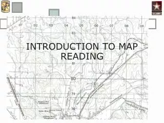
Map Reading I. Marginal Information. Tenino. Sheet Name Sheet Number Adjoining Map Sheets Diagram Stock Number. Edition 7-DMATC Series V791 Sheet 1477 IV. Marginal Information (2). Declination Diagram Special Notes. Marginal Information (3). Scale Bar Scales

Map Reading I
E N D
Presentation Transcript
Marginal Information Tenino • Sheet Name • Sheet Number • Adjoining Map Sheets Diagram • Stock Number Edition 7-DMATC Series V791 Sheet 1477 IV
Marginal Information (2) • Declination Diagram • Special Notes
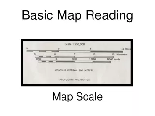
Marginal Information (3) • Scale • Bar Scales • Contour Interval Notes • Grid Reference Box
Marginal Information (4) • Map Agency • Legend
Colors on a Military Map (IAW FM 3-25.26 (C1), dated 30 August 2006) • Black: Indicates cultural (man-made) features such as buildings and roads, surveyed spot elevations, and all labels. • Red-Brown: The colors red and brown are combined to identify cultural features, all relief features, non-surveyed spot elevations, and elevation such as contour lines on red-light readable maps. • Blue: Identifies hydrography or water features such as lakes, swamps, rivers, and drainage. • Green: Identifies vegetation with military significance such as woods, orchards, and vineyards. • Brown: Identifies all relief features and elevation such as contours on older edition maps and cultivated land on red-light readable maps. • Red: Classifies cultural features, such as populated areas, main roads, and boundaries, on older maps.
Terrain Features Five Major • Ridge • Hill • Saddle • Valley • Depression Three Minor • Draw • Spur • Cliff Two Supplemental • Cut • Fill
Cut I
Military Grid Reference System The MGRS is the geocoordinate standard for NATO for locating points on the earth. The grid coordinate is made up of three parts: The Grid Zone Designation – one/two numbers followed by a letter identifies the UTM zone (numbers) and the latitude band (letter) The 100,000-meter Square Identifier – two letters identifying the series of 100,000-meter squares subdividing the UTM zones The Numerical Location – a series of even numbers to identify the location within the 100,000-meter square Grid Zone 100,000-meter 4 Digit 6 Digit 8 Digit 10 digit Designation Square Location Location Location Location State County Town Neighborhood Yard Tree 6o X 8o @ 10 KM2 1 KM2 100 M2 10 M2 1 M2 @ 675 KM2
100,000-meter Square Identifiers
Determining Grid Coordinates • Select the correct scale on the protractor • Place the horizontal scale on the grid line with the “0 mark” at the lower left-hand corner of the grid square. • Slide scale right into until the vertical scale intersects the center of your plot point • Read right then read up
SAMPLE 1,000 METER GRID SQUARE 46 SAMPLE POINT X 45 12 13 100,000 M SQUARE IDENTIFICATION EH EG GRID ZONE DESIGNATOR 10T Four-Digit Grid Coordinates 10T EG 05 80 1) Identify the 100,000 Square Identification Letters (in the Grid Reference Box). 2) Read Right to the last grid before your point. 3) Read Up to the last east-west grid below or before your point. Then Up ReadRight
Zero “0” Mark 1000 9 8 7 10T EG 05 80 6 5 Place your protractor scale on the Zero-Mark 4 3 2 1 0 2 1 0 1000 9 8 7 6 5 4 3
SAMPLE 1,000 METER GRID SQUARE 46 SAMPLE POINT X 45 12 13 100,000 M SQUARE IDENTIFICATION EH EG GRID ZONE DESIGNATOR 10T Six-Digit Grid Coordinates 10T EG 055 804 1000 9 8 7 6 5 4 3 2 1 0 2 1 0 1000 9 8 7 6 5 4 3
SAMPLE 1,000 METER GRID SQUARE 46 SAMPLE POINT X 45 12 13 100,000 M SQUARE IDENTIFICATION EH EG GRID ZONE DESIGNATOR 10T Eight-Digit Grid Coordinates 10T EG 0557 8046 1000 9 8 7 6 5 4 3 2 1 0 2 1 0 1000 9 8 7 6 5 4 3
SAMPLE 1,000 METER GRID SQUARE 46 SAMPLE POINT X 45 12 13 100,000 M SQUARE IDENTIFICATION EH EG GRID ZONE DESIGNATOR 10T What is the grid coordinate of Hill 141? 10T EG 05 57 80 46
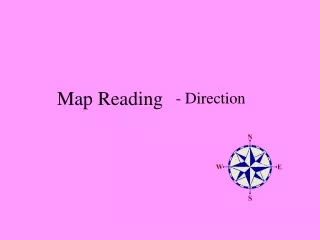
Determining Azimuths Mils Scale Degrees Scale 45° 120° 225°
Determining a Grid Azimuth 03 02 01 x 57° 00 99 98 97 x 10 11 12 1314 15 16 17
Converting Azimuths Tenino Map Sheet Easterly Declination Sample (Michigan – South Carolina) Westerly Declination Tenino
What is the grid azimuth from Hill 141 to Hill 144? 48 degrees What is the back azimuth for 48 degrees? 228 degrees