Download
1 / 23
230 likes | 329 Vues
Comprehensive analysis of splice mapping results in Sector 12 circuits, including tests on RB and RQ circuits. Special PLI2 s1 tests conducted, documenting current steps, ramp rate, and plateau times. Signals transferred for analysis via QPS supervision and TIMBER. Detailed findings on bus-bar protection layouts, voltage drops, and resistance measurements. Bus segment resistance measurements show promising results, while inductance compensation is still in progress. Snapshots of RB and RQ circuits provide visual documentation. Future steps include nQPS-IST testing and protection implementation.

E N D
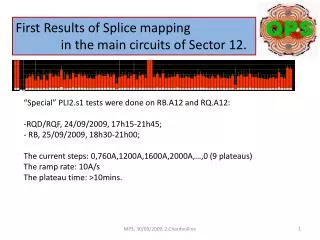
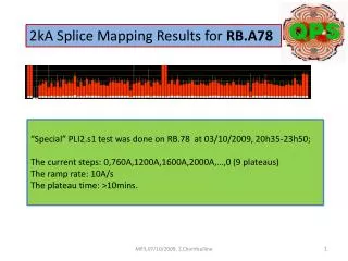
First Results of Splice mapping in the main circuits of Sector 12. • “Special” PLI2.s1 tests were done on RB.A12 and RQ.A12: • RQD/RQF, 24/09/2009, 17h15-21h45; • RB, 25/09/2009, 18h30-21h00; • The current steps: 0,760A,1200A,1600A,2000A,…,0 (9 plateaus) • The ramp rate: 10A/s • The plateau time: >10mins. MP3, 30/09/2009, Z.Charifoulline
nQPS layout for bus-bar protection – example (R.Denz, MP3, 19/08/2009) “U_MAG” – magnet signal, which is total voltage drop on the “reference” magnet; “U_RES = Ubus–α*U_MAG” - bus bar signal; α=93.0E-5 (dipoles) and α=51.0E-3 (quads) – defaults values for dI/dt compensation; • _SPLICE signals are sent directly to analysis tools via special subscription to QPS supervision signals (developing by Odd Andreassen, additional few weeks?) • All signals are transferred to QPS supervision and TIMBER, certain status flags as well to LASER • All signals are recorded on change; dead-bands apply only to LSB • LSB U_RES = 1.5 nV(24bit, ±12.5mV) • LSB U_MAG = 305 nV MP3, 30/09/2009, Z.Charifoulline
nQPS layout for bus-bar protection – example (R.Denz, MP3, 19/08/2009) “U_MAG” – magnet signal, which is total voltage drop on the “reference” magnet; “U_RES = Ubus–α*U_MAG” - bus bar signal; α=93.0E-5 (dipoles) and α=51.0E-3 (quads) – defaults values for dI/dt compensation; • _SPLICE signals are sent directly to analysis tools via special subscription to QPS supervision signals (developing by Odd Andreassen, additional few weeks?) • All signals are transferred to QPS supervision and TIMBER, certain status flags as well to LASER • All signals are recorded on change; dead-bands apply only to LSB • LSB U_RES = 1.5 nV(24bit, ±12.5mV) • LSB U_MAG = 305 nV U_RES_SPLICE(I) = U0 + Rbus*I + {∆α*U_MAG_SPLICE(I)}; U_MAG_SPLICE(I) = U0 + Rmag*I; MP3, 30/09/2009, Z.Charifoulline
A12.RQD/RQF: U_RES_SPLICE vs Time & I_MEAS vs Time MP3, 30/09/2009, Z.Charifoulline
A12.RQD/RQF: U_RES_SPLICE vs Time & I_MEAS vs Time MP3, 30/09/2009, Z.Charifoulline
A12.RQD/RQF: U_RES_SPLICE vs I_MEAS MP3, 30/09/2009, Z.Charifoulline
A12.RQD/RQF: BusSegmentReistancevsnQPS Crate MP3, 30/09/2009, Z.Charifoulline
A12.RQD/RQF: BusSegmentReistancevsnQPS Crate MP3, 30/09/2009, Z.Charifoulline
A12.RQD/RQF: BusSegmentReistancevsnQPS Crate MP3, 30/09/2009, Z.Charifoulline
A12.RQD/RQF: BusSegmentReistancevsnQPS Crate MP3, 30/09/2009, Z.Charifoulline
A12.RQD/RQF: BusSegmentReistancevsnQPS Crate MP3, 30/09/2009, Z.Charifoulline
A12.RQD/RQF: BusSegmentReistancevsnQPS Crate MP3, 30/09/2009, Z.Charifoulline
A12.RQD/RQF: BusSegmentReistancevsnQPS Crate 8 32 18 8 14 Thanks to C.Lorin, F.Bertinelli for Splice Num Mapping MP3, 30/09/2009, Z.Charifoulline
A12.RQD/RQF: BusSegmentReistancevsnQPS Crate 8 32 18 8 14 Thanks to C.Lorin, F.Bertinelli for Splice Num Mapping MP3, 30/09/2009, Z.Charifoulline
A12.RB: BusSegmentReistancevsnQPS Crate (current flow) MP3, 30/09/2009, Z.Charifoulline
A12.RB: BusSegmentReistancevsnQPS Crate (current flow) Thanks to C.Lorin, F.Bertinelli for Splice Num Mapping MP3, 30/09/2009, Z.Charifoulline
A12.RB: BusSegmentReistancevsnQPS Crate (current flow) Thanks to C.Lorin, F.Bertinelli for Splice Num Mapping MP3, 30/09/2009, Z.Charifoulline
32 splices MP3, 30/09/2009, Z.Charifoulline
Sector A12, nQPS, Preliminary conclusion (29/09/2009): • bus segments resistance measurement based on U_RES signals looks very promising; • inductance compensation works well and almost done, there are few units to be fixed; • next step will be to perform nQPS-IST and switch on the protection, I think; • but, magnets resistance measurements based on U_MAG signals are noisy and not yet fully • analyzed to be interpreted correctly; MP3, 30/09/2009, Z.Charifoulline
A12.RB: Snapshots MP3, 30/09/2009, Z.Charifoulline
A12.RB: Snapshots MP3, 30/09/2009, Z.Charifoulline
A12.RQD/F: Snapshots MP3, 30/09/2009, Z.Charifoulline
A12.RQD/F: Snapshots MP3, 30/09/2009, Z.Charifoulline


![High-Throughput Analysis of Genomic Data [S7] E NRIQUE B LANCO](https://cdn2.slideserve.com/3859222/high-throughput-analysis-of-genomic-data-s7-e-nrique-b-lanco-dt.jpg)