Download
1 / 14
140 likes | 245 Vues
Simulation study on Ground Motion & Vibration Transfer Function for QD0/SD0 Cryomodule System at ILC, focusing on beamlines, feedback mechanisms, and impact on luminosity loss prevention. Results analyzed for different GM models.

E N D
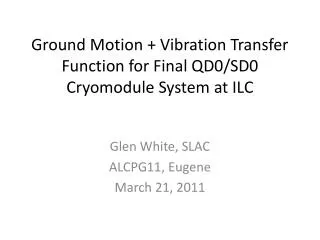
Ground Motion + Vibration Transfer Function for Final QD0/SD0 Cryomodule System at ILC Glen White, SLAC ALCPG11, Eugene March 21, 2011
Simulation Overview • Lucretia simulation of ILC BDS • ILC2006e (RDR) lattice and beam parameters • Reduce Nb 2625 -> 1320 for luminosity calculation with fast feedback to more closely mimic SB2009 parameter set • Electron and positron beamlines • Ground motion applied to allILCelements plustransfer function (TF) between ground and QD0/SD0/OC0 system. • 50consecutive pulses (10s) modelled with ground motion + pulse-pulse feedback. • Results shown for GM models ‘A’, ‘B’ and ‘C’ • QD0 system TF calculation forSiD “rigid supportfrom platform” (Marco). • Fast IP position feedback for tolerance estimates. • Simplifications • RTML and Linac excluded fromtracking simulation • Incoming beam perfectly aligned with first element (upstream FFB) • No intra-pulse misalignments • No other mechanical noise model of magnets applied
Simulation Parameters • Initially perfect lattice. • BPMs • Cavity systems throughout BDS • Resolution = 100nm • Scale factor error = 1% • StriplineBPMs for fast feedback • Resolution = 2um • Scale factor error = 1% • Corrector magnet field errors 0.1% • 5 Hz feedback • Simple gain feedback, convergence 50 pulses • Intra-pulse feedback • Based on detection of beam-beam kick at IP for small offsets using downstream stripline BPM and correction using stripline kicker system between QF1 & QD0 cryomodule systems • Feedback is PID controller using linearised look-up of beam-beam kick to IP beam offset model (up to turn-over point). Feedback convergence ~20bunches for offsets left of turn-over point.
IP Region Final Doublet BPM BPM SF1 QF1 SD0 QD0 IP -> IP FB Kicker OCT OCT TF to ground (from detector model) This and other magnets assumed rigidly attached to ground
Ground Motion Spectra • The simulation applies offsets due to ground motion according to Model ‘A’, ‘B’ or ‘C’ • The spectra for these models indicative of ‘quiet’, ‘average’ and ‘noisy’ sites, mainly in terms of the magnitude of high frequency noise, are shown above
Simulated GM Example (‘C’) • 10s of ‘C’ GM showing ground position change and beam orbits • Tracking studies focused on BDS section
QD0 TF • “Rigid support structure” model from SiD group (Marco). QD0 rigidly attached to detector platform. • Apply to simulation girder element attached to SD0/OC0/QD0 cryomodule.
GM Induced Jitter @ IP (Vertical Offset between e- and e+ beams at IP) with and without QD0 TF GM ‘C’ GM ‘B’ GM ‘A’
Luminosity Loss Mechanisms and Preventative Feedbacks • Ground motion causes misalignment of all BDS magnets, causing growth of beam orbit over time • 2 mechanisms for Luminosity loss • Beamsize growth at IP • Orbit generates emittance growth due to dispersive kicks along the beamline • Offsets in non-linear elements cause larger beamsize at IP through introduction of linear and higher order aberations (mainly waist offset, dispersion and coupling) • Beams move out of collision in position and angle at IP • Slow orbit feedbacks keep beamsize effects from becoming too large • Still residual pulse-pulse jitter at IP, this must keep within the tolerances of the intra-pulse feedback system (ideally ~<200nm) • Intra-pulse feedbacks keep beams in collision. • Depends on shape of pulse train, incoming conditions etc which are hard to model. Model a conservative case tuned to deal with harsh conditions. • Performance limited by speed of convergence (governed by intra-pulse jitter conditions and pulse shape reproducibility) andbeamsize growth due to correction kick induced offset through SD0(depends on the size of the required correction (IP offset)).
Intra-Pulse IP Feedback • Use ILC IP FFB, tuned for ‘noisy’ conditions (like those simulated for TESLA) • Assume BDS-entrance FFB has perfectly flattened beam train (flat trajectory into Final Doublet). • Nosystematic or randomintra-pulse distortions. • Calculate Luminosity from measured bunches, with mean of last 50 weighted to account for the rest of the beam train (1320 bunches).
Luminosity Loss vs. QD0 Jitter • Data shown gives % nominal luminosity for different levels of uncorrelated QD0 jitter. • 100 pulses simulated per jitter cases with FFB • Mean, 10% & 90% CL results shown for each jitter point from 100 pulse simulations • Tolerance to keep luminosity loss <1% is <50nm RMS QD0 jitter.
Mechanical Jitter of Magnets • GM ‘C’ + QD0 TF + mechanical jitter added to all BDS magnets • Could tolerate -> 17nm RMS additional mechanical magnet jitter. / nm
Scaling of TF Magnitude • Scale magnitude of TF attached to QD0 • Can be scaled by -> 120% before required 50nm RMS IP offset jitter exceeded.
Conclusions • In the worst GM model considered (‘C’), the QD0 TF studied increases expected jitter of QD0 magnet from 19.4 -> 24.3 nm • The effect in GM Models ‘A’ and ‘B’ is negligible. • The jitter tolerance to keep luminosity loss <1% is <50nm RMS • The TF studied meets this requirement in the worst studied GM case. • Can scale magnitude of provided TF up to 120% before exceeding tolerance. • This assumes no other mechanical vibration • For GM ‘C’ and the studied TF, up to a further 17nm RMS jitter can be tolerated whilst keeping within the 50nm tolerance.