Download
1 / 75
2.36k likes | 4.58k Vues
Fundamentals of Geometric Dimensioning & Tolerancing. Overview. Definition and Background Features and Datums Datum Reference Frame How the GD&T System Works Material Conditions Modifiers Bonus Tolerance Feature Control Frame Major Categories of Tolerances

E N D
Fundamentals of Geometric Dimensioning & Tolerancing
Overview • Definition and Background • Features and Datums • Datum Reference Frame • How the GD&T System Works • Material Conditions Modifiers • Bonus Tolerance • Feature Control Frame • Major Categories of Tolerances • 14 Tolerance Measurements • General Rules of GD&T • + /- Tolerancing vs. Geometric Tolerancing
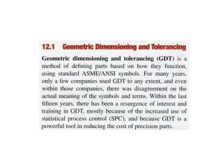
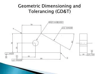
The GD&T Process • What is GD&T ? • Geometric Dimensioning and Tolerancing - Uses standard, international symbols to describe parts in a language that is clearly understood by any manufacturer. This simple drawing shows many of the symbols that define the characteristics of a workpiece and eliminates the need for traditional handwritten notes.
The GD&T Process (con’t) • A significant improvement over traditional dimensioning methods in describing form, fit and function of parts. • Considered a mathematical language that is very precise. • Describes each workpiece in three “zones of tolerance” relative to the Cartesian Coordinate System. • A little history: • Developed by Rene Descartes (pronounced day-kart), a French mathematician, philosopher and scientist. • Descartes (Renatus Cartesius - Latin) born in 1596 in France and died in 1650. • Formed much of the thought about the order of things in the world. • Established three precepts about the method by which we should examine all things.
The GD&T Process (con’t) “Never accept anything for true which you do not clearly know to be such.” • First precept was most important: This idea may have been the starting point for the development of modern science. That idea of examining everything in relation to what should be “exact and perfect” led to Descartes’ development of the Cartesian Coordinate System – a coordinate plane to make it easier to describe the position of objects.
The GD&T Process (con’t) • GD&T has developed as a method to question and measure the “truth” about the form, orientation, and location of manufactured parts. • Like other languages, GD&T uses special punctuation and grammar rules. • Must be used properly in order to prevent misinterpretation. • Comparable to learning a new language.
The GD&T Process (con’t) • Background: • Standards come from two organizations: * ASME (American Society of Mechanical Engineering) * ISO (International Organization for Standardization) - ASME Y14.5 and ISO 1101 are the written standards. - Gives inspectors a clear understanding of what the designer intended.
The GD&T Process (con’t) • When Should GD&T be Used : • When part features are critical to function or interchangeability. • When functional gauging techniques are desirable. • When datum references are desirable. • When computerization techniques are desirable. • When standard interpretation or tolerance is not already implied. • Why Should GD&T be Used: • It saves money. • Provides for maximum producibility of parts. • Insures that design tolerance requirements are specifically stated and carried out. • Adapts to, and assists, computerization techniques. • Ensure interchangeability of mating parts at assembly. • Provides uniformity and convenience in drawing.
GOOD The GD&T Process (con’t) • Advantages of GD&T: • Significant improvement over traditional methods. • Compact language, understood by anyone who learns the symbols. • Replaces numerous notes. • Offers greater design clarity, improved fit, better inspection methods, and more realistic tolerances. • Ensure that: • Good parts pass inspection. • Bad parts are caught and rejected.
Common Tolerance Symbols We will discuss examples of these symbols as we proceed with the course.
Understanding the Terms • Radius – Two types of radii can be applied. The radius (R) distinguishes general applications. The controlled radius (CR) defines radius shapes that require further restrictions. • Statistical Tolerancing Symbol - Tolerances are sometimes calculated using simple arithmetic. If a part is designated as being statistically toleranced, it must be produced using statistical process controls. • With Size – A feature said to be “with size” is associated with a size dimension. It can be cylindrical or spherical or possibly a set of two opposing parallel surfaces. • Without Size – A plane surface where no size dimensions are indicated. • Feature Control Frames – Probably the most significant symbol in any geometric tolerancing system. Provides the instructions and requirements for its related feature. • Material Condition Modifiers – Often necessary to refer to a feature in its largest or smallest condition or regardless of its feature size. • MMC (Maximum Material Condition) • LMC (Least Material Condition) • RFS (Regardless of Feature Size)
Datums and Features • All manufactured parts exist in two states: - The imaginary, geometrically perfect design - The actual, physical, imperfect part. DATUMS: • A part design consists of many datums (each is a geometrically perfect form). • Datums can be : - straight lines - circles - flat planes - spheres - cylinders - cones - a single point
Datums and Features (con’t) • Datums are “imaginary”. They are assumed to be “exact” for the purpose of computation or reference. • Utilizing datums for reference, the tolerances take on new meaning. • Now, features can have a tolerance relationship to each other both in terms of form and also location.
Datums and Features (con’t) • Features: • Real, geometric shapes that make up the physical characteristics of a part. • May include one or more surfaces: • Holes • Screw threads • Profiles • Faces • Slots • Can be individual or may be interrelated. • Any feature can have many imperfections and variations.
Datums and Features (con’t) • Tolerances in a design tell the inspector how much variance or imperfection is allowable before the part must be considered unfit for use. • Tolerance is the difference between the maximum and minimum limits on the dimensions of the part. • Since parts are never perfect, a datum feature is used during inspection, to substitute for the perfect datum of the drawing. • Datum features are simply referred to as datums. We cannot make a “perfect” part.
profile and position The Datum Reference Frame • GD&T positions every part within a “Datum Reference Frame”. • The DRF is by far the most important concept in the geometric tolerancing system. • The skeleton, or frame of reference to which all requirements are connected. • Understanding the DRF is critical in order to grasp the concepts of
The Datum Reference Frame (con’t) • Engineering, manufacturing, and inspection all share a common “three plane” concept. • These three planes are: • Mutually perpendicular • Perfect in dimension and orientation • Positioned exactly 900 to each other. • This concept is called the Datum Reference Frame.
The Datum Reference Frame (con’t) • The three main features of the DRF are the planes, axes, and points. • The DRF consists of three imaginary planes, similar to the X, Y, & Z axes of the traditional coordinate measuring system. • The planes exist only in theory and make up a perfect, imaginary structure that is mathematically perfect. • All measurements originate from the simulated datum planes. This flat, granite surface plate and the angle block sitting on it , can represent two of the three datum planes.
The Datum Reference Frame (con’t) • The Datum Reference Frame will accommodate both rectangular and cylindrical parts. • A rectangular part fits into the corners represented by the inter- section of the three datum planes. • The datum planes are imaginary and therefore perfect. • The parts will vary from these planes, even though the variations will not be visible to the naked eye. • The most important concept to grasp is that when the part is placed into an inspection apparatus, it must make contact with the apparatus planes in the order specified by the feature control frame. (Primary, then secondary, then tertiary). This is the only way to assure uniformity in the measurement of different parts.
The Datum Reference Frame (con’t) • A cylindrical part rests on the flat surface of the primary plane and the center of the cylinder aligns with the vertical datum axis created by the intersection of the planes. • In this case, it becomes very important to be able to establish the exact center of the part, whether it is the center of a solid surface, or the center of a hole. • Cylindrical parts are more difficult to measure.
Implied Datums • The order of precedence in the selection and establishment of datums is very important. • The picture below shows a part with four holes, located from the edges with basic dimensions. • The datums are not called out in the feature control frame, but they are “implied” by the dimensions and by the edges from which those dimensions originate. Thus, we imply that these edges are the datums.
Implied Datums (con’t) • Problems with implied datums: • We do not know the order in which they are used. • We know the parts are not perfect. • None of the edges are perfectly square. • The 90o corners will not be perpendicular. • In theory, even if the corners were out of perpendicularity by only .0001, the part would still “rock” back and forth in the “theoretically perfect” datum reference frame.
The Order of Datums • GD&T instructions designate which feature of the part will be the “primary, secondary, or tertiary” datum references. • These first, second and third datum features reflect an order of importance when relating to other features that don’t touch the planes directly. • Datum orders are important because the same part can be inspected in several different ways, each giving a different measurement. Creating a Datum Reference Frame and an order of importance is mandatory in order to achieve interchangeable parts. Improper positioning could result in measurement errors unless the preferred positioning in the inspection fixture is indicated in the drawing.
The Order of Datums (con’t) • The primary datum feature must have at least three points of contact with the part and contacts the fixture first. • The secondary has two points of contact and the tertiary has three points of contact with the part. • This process correctly mirrors the datum reference frame and positions the part the way it will be fitted and used.
SECTION 2 - HOW THE GEOMETRIC SYSTEM WORKS • This section introduces the geometric system and explains the major factors that control and/or modify its use. • Those important factors are: • Plus/Minus Tolerancing • Geometric Tolerance Zones • The difference between geometric and limit tolerancing. • Material Condition Modifiers • Bonus Tolerance • The Feature Control Frame
Plus / Minus Tolerancing • Plus/ Minus tolerancing, or limit tolerancing is a two-dimensional system. • When the product designer, using drafting or CAD equipment draws the part, the lines are straight, angles are perfect, and the holes are perfectly round. • When the part is produced in a manufacturing process, there will be errors. • The variations in the corners and surfaces will be undetectable to the human eye. • The variations can be picked up using precise measurements such as a CMM.
Plus / Minus Tolerancing (con’t) • In a plus/minus tolerancing system, the datums are implied and therefore, are open to varying interpretations. • Plus/minus tolerancing works well when you are considering individual features. However, when you are looking at the relationship between individual features, plus/minus tolerancing is extremely limited. • With the dawn of CAD systems and CMMs, it has become increasingly important to describe parts in three dimensional terms, and plus/minus tolerancing is simply not precise enough.
Geometric Tolerance Zones • A geometric tolerancing system establishes a coordinate system on the part and uses limit tolerancing to define the form and size of each feature. • Dimensions are theoretically exact and are used to define the part in relation to the coordinate system. • The two most common geometric characteristics used to define a feature are position and profile of the surface.
Geometric Tolerance Zones (con’t) • Referring to the angle block below, position tolerance is located in the first block of the feature control frame. It specifies the tolerance for the location of the hole on the angle block. The “boxed dimensions” define what the exact location of the center of the hole should be. 1.000 x 1.500. The position tolerance block states that the center of the hole can vary no more than .010 inches from that perfect position, under Maximum Material Condition. The position tolerance zone determines the ability of the equipment used to produce the part within limits. The tighter the position tolerance is, the more capable the equipment. Position tolerance is merely a more concise manner in which to communicate production requirements.
Geometric Tolerance Zones (con’t) • Profile tolerance(half-circle symbol) is specified in the second block of the feature control frame. It is used to define a three dimensional uniform boundary that the surface must lie within. The tightness of the profile tolerance indicates the manufacturing and verification process. Unimportant surfaces may have a wide tolerance range, while important surfaces will have a very tight profile tolerance range. • Form tolerance refers to the flatness of the part while orientation tolerance refers to the perpendicularity of the part specified on the datums. These two tolerances are chosen by the designer of the part in order to match the functional requirements of the part. Form and orientation tolerances control the instability of the part.
Geometric vs. Bilateral, Unilateral & Limit Tolerancing • The difference between “geometrically toleranced” parts and “limit toleranced” parts is quite simple. Geometric tolerances are more precise and clearly convey the intent of the designer, using specified datums. It uses basic dimensions which are theoretically exact and have zero tolerance. • Limit tolerancing produces a part that uses implied datums and larger, less exact tolerances that fall into three basic categories: • Bilateral tolerancesspecify the acceptable measurements in two opposite directions from a specified dimension. • Unilateral tolerances define the acceptable range of measurements in only one direction from a given dimension. • Limit dimensions give the acceptable measurements within two absolute dimensions.
.245 .255 .250 + .005 .250 + .005 Material Condition Modifiers • Used in geometric tolerancing. • Have tremendous impact on stated tolerance or datum reference. • Can only be applied to features and datums that specify size. (holes, slots, pins, tabs). If applied to features that are without size, they have no impact. • If no modifier is specified in the feature control frame, the default modifier is “RFS” – regardless of feature size. • There are three material condition modifiers: • Maximum Material Condition– (MMC) – This modifier gives room for additional position tolerance of up to .020 as the feature departs from the maximum material condition. This is a condition of a part feature wherein, it contains the maximum amount of material, or the minimum hole-size and maximum shaft-size. Emphasis is on the word “Material”.
.255 .245 .250 + .005 .250 + .005 Material Condition Modifiers (con’t) • Least Material Condition– (LMC) – This is the opposite of the MMC concept. This is a part feature which contains the least amount of material, or the largest hole-size and smallest shaft-size. • Regardless of Feature Size– (RFS) – This is a term used to indicate that a geometric tolerance or datum reference applies at any increment of size of the feature within its size tolerance. RFS is stricter and greatly affects the part’s function, but is necessary for parts that require increased precision.
Bonus Tolerance • Material condition modifiers give inspectors a powerful method of checking shafts and holes that fit together. • Both MMC and LMC modifiers allow for bonus tolerance. • This hole has a certain position tolerance, but at MMC, the hole is smaller, tighter, and exhibits a perfect cylindrical form. • As more material is removed from around the hole, the space is larger and provides a looser fit for the shaft. Therefore, the position tolerance for the hole can be increased, and both the shaft and the hole will still fit. This increased tolerance is called the bonus tolerance of the hole and changes as the size of the hole increases. Hole drilled at MMC Bonus Tolerance Hole drilled at LMC
The Feature Control Frame • GD&T instructions contain a large amount of information. • Each feature is given a feature control frame. • Frame reads from left to right, like a basic sentence. • Instructions are organized into a series of symbols that fit into standardized compartments.
The Feature Control Frame (con’t) • The first compartment defines the geometric characteristic of the feature, using one of the 14 standard geometric tolerance symbols ( means “position”). A second feature control frame is used if a second geometric tolerance is needed. • The second compartment contains the entire tolerance for the feature, with an additional diameter symbol to indicate a cylindrical or circular tolerance zone. No additional symbol is needed for parallel lines or planes. If needed, material condition modifiers would also appear in the second compartment.
The Feature Control Frame (con’t) • The third compartment indicates the primary datum which locates the part within the datum reference frame. Every related tolerance requires a primary datum but independent tolerances, such as form tolerances, do not. • The fourth and fifth compartments contain the secondary and tertiary datums. Depending on the geometric tolerance and the function of the part, secondary and tertiary datums may not be necessary.
Section 3 Straight & Cylindrical Tolerances • Types of Tolerances – 5 major groups. - Form Tolerances (flatness, circularity, cylindricity & straightness. - Profile Tolerances (profile of surface, profile of line). Powerful tolerances that control several aspects. - Orientation Tolerances (perpendicularity, parallelism, and angularity). - Location Tolerances (concentricity, symmetry, and position). - Runout Tolerances (circular and total). Used only on cylindrical parts.
Straight & Cylindrical Tolerances (con’t) An individual tolerance is not related to a datum. A related tolerance must be compared to one or more datums.
Straightness and Flatness • Two types of form tolerances. Both define a feature independently. - Straightness is a two-dimensional tolerance. Edge must remain within two imaginary parallel lines to meet straightness tolerance. Distance between lines is determined by size of specified tolerance. - Most rectangular parts have a straightness tolerance. - Edge or center axis of a cylinder may have a straightness tolerance. Greatly exaggerated
Straightness and Flatness (con’t) • Flatness is a three-dimensional version of straightness tolerance. - Requires a surface to be within two imaginary, perfectly flat, perfectly parallel planes. - Only the surface of the part, not the entire thickness, is referenced to the planes. - Most often used on rectangular or square parts. - If used as a primary datum, flatness must be specified in the drawing.
Circularity and Cylindricity • Circularity(often called roundness). - Two-dimensional tolerance. - Most often used on cylinders. - Also applies to cones and spheres. - Demands that any two-dimensional cross-section of a round feature must stay within the tolerance zone created by two concentric circles. - Most inspectors check multiple cross-sections. - Each section must meet the tolerance on its own.
Circularity and Cylindricity (con’t) • Cylindricity specifies the roundness of a cylinder along its entire length. - All cross-sections of the cylinder must be measured together, so cylindricity tolerance is only applied to cylinders. • Circularity and cylindricity cannot be checked by measuring various diameters with a micrometer. • Part must be rotated in a high-precision spindle. Best method would be to use a Coordinate Measuring Machine (CMM). The thickness of the wall of a pipe represents the cylindricity tolerance zone.
Profile of a Line and Surface • The two versions of profile tolerance. • Both can be used to control features such as cones, curves, flat or irregular surfaces, or cylinders. • A profile is an outline of the part feature in one of the datum planes. • They control orientation, location, size and form. • The profile of a line is a two-dimensional tolerance. - It requires the profile of a feature to fall within two imaginary parallel lines that follow the profile of the feature.
Profile of a Line and Surface (con’t) • Profile of a Surface is three-dimensional version of the line profile. - Often applied to complex and curved contour surfaces such as aircraft and automobile exterior parts. - The tolerance specifies that the surface must remain within two three-dimensional shapes.
Section 4 Orientation and Location Tolerances • Angularity, Perpendicularity, and Parallelism - These tolerances define the angle and orientation of features as they relate to other features. - They specify how one or more datums relate to the primary toleranced feature. (Relational Tolerances) Angularity - A three-dimensional tolerance. * Shape of the tolerance zone depends on shape of the feature. * If applied to flat surface, tolerance zone becomes two imaginary planes, parallel to ideal angle. * If applied to a hole, it is referenced to an imaginary cylinder existing around the ideal angle and center of the hole must stay within that cylinder.
Orientation and Location Tolerances (con’t) • Perpendicularity and Parallelism :Three-dimensional tolerances that use the same tolerance zones as angularity. • Difference is that parallelism defines two features that must remain parallel to each other, while perpendicularity specifies a 90-degree angle between features. Perpendicularity Parallelism
Orientation and Location Tolerances (con’t) • Parallelism and Flatness are often confused. - Flatness is not related to another datum plane. • When an orientation tolerance is applied to a flat surface, it indirectly defines the flatness of the feature.
Orientation and Location Tolerances (con’t) • Position is one of most common location tolerances. - A three-dimensional, related tolerance. - Ideal, exact location of feature is called true position. - Actual location of a feature is compared to the ideal true position. - Usually involves more than one datum to determine where true position should be. - Has nothing to do with size, shape, or angle, but rather “where it is”.
Orientation and Location Tolerances (con’t) • In the case of holes, the tolerance involves the center axis of the hole and must be within the imaginary cylinder around the intended true position of the hole. • If toleranced feature is rectangular, the zone involves two imaginary planes at a specified distance from the ideal true position. • Position tolerance is easy to inspect and is often done with just a functional gage (go / no-go gage).