LightABLE Production Status
This report, presented by Tony Weidberg, outlines the current production status for the LightABLE VCSEL array project as of May 2014. The project aims to enhance reliability through commercial packaging and effective PCB integration. Key updates include issues with the assembly company leading to delayed deliveries, a total of 363 LightABLEs delivered out of 500 ordered, ongoing QA processes, and performance measurements. Major mechanical and thermal management changes have been implemented to ensure effective operation. Future plans involve finalizing production and expanding installation.

LightABLE Production Status
E N D
Presentation Transcript
LightABLE Production Status ID Week May 2014 Tony Weidberg
LTx Project • Aim: use commercial package for VCSEL array to improve reliability. • Integration into fully backward compatible TX PCB • Electrical and optical connections • Space constraints LightABLE OSA (Reflex Photonics) Tony Weidberg
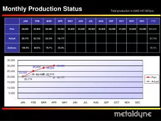
Production Status • 363 LightABLEs delivered (500 ordered). • Delivery late because of problems with the assembly company. • Final batch now promised for end May. • Two flavours of PCB produced and components mounted (except LightABLE). • > 301 LTx assembled. • 101wire bonded • 84 completed burn-in • Production rate between 20 to 40/ week. Tony Weidberg
Power QA @ Oxford • DC power only at this stage • Problem is that LightABLE devices have large offset power and we only use modulation (ac coupled links). • Better power QA @ Cambridge Tony Weidberg
Change after Burn-in • Burn-in: 72 hours @ 70c and 10 mA drive current • No large changeobserved. • Need to re-measure one underflow Tony Weidberg Change (dB)
Cambridge QA • Based on existing system to test AC performance • Loopback test TX RX • Measure BER and perform timing scan width of eye diagram • Measure power while adjusting modulation amplitude • requires programming uProc on LightABLE • Trick to deal with large baseline power (resistors added to DRX-12 to bleed current). • Work in progress … Tony Weidberg
Plans • Complete production and QA for LTx • Develop BOC s/w to allow operation of LTx or AOC. • Install LTx in one crate in June. • Check performance • Ipin • BER in physics mode tests • Install LTx in more crates ? Tony Weidberg
Backup Tony Weidberg
Changes Since Design Review • Essential: • Make it easier for Infineon SMC connector to connect to LTx in USA15 • Improve thermal management • Highly desirable: Allow option of decreasing optical power from LTx in case of saturation for DORIC4A. • Mechanical reliability, consider use of under-fill for LightABLE BGA. Tony Weidberg
Mechanical Changes • Make mate/demate with Infineon SMC easier. • Shortened length of MT guide pins. • Added groove near end that was cut to help with gluing. End sticking out is the uncut end. • Use long guide pins in jig during reflow. Ensures that guide pins will be in the correct location and pointing the correct way. Tony Weidberg
Underfill • Decided against use of underfillfor BGA • Mismatch in CTE. • Very little insertion force required. • 100 mate/demate cycles with monitoring of power every 10 cycles no changes • Thermal cycling: no change in power. Tony Weidberg
Cooling • Thermal path from LightABLE to front panel via Thermal Gap Filler (3 Wm/K) • OSA analysis DT from junction to ambient =20°C ( next slide). Tony Weidberg
OSA Analysis • Measure Peak wavelength lp • Scan Mark: Space Ratio (MSR) and measure lp • Plot lp versus MSR • Fit slope and extrapolate to 50%. • Use calibration dlp/dT DT • Fit Results variable in quality but reasonable consistency Tony Weidberg
AtLinksLightABLE- uProc Maurice Goodrick • We can use a microprocessor to drive the LightABLE Engine’s I2C inputs, and the SPI lines currently used for the MDACs can be used to drive the µProc • But the MDACS we must still give the right output current for the interface circuit • This could be done using the µProc’s SPI lines • It could be carried out when the µProc is initialised • The MDAC_CLR command (one of the BOC_SPI signals) could be used to force a uProc initialisation • This is what it would look like: Tony Weidberg
Maurice Goodrick AtLinksLightABLE- uProc Connections Z PCB Tony Weidberg
QA: Optical Power <Optical Power> @ 50% duty cycle, after burn-in Change with burn-in (72 hours @70C) Tony Weidberg
LTx in SR1 • LTx optical power. • No T correction • Initial decrease ~1%. • No burn-in preformed for this array probably ok but should run longer Steve McMahon Optical Power (mV) Tony Weidberg Time (days)
Steve McMahon Optical Power (mV) Time (days) Tony Weidberg
Summary • Improvements following design review have been implemented. • Production well underway. • Populate one crate in USA-15 in May • Need to continue long-term optical power monitoring in SR1 and USA-15. Tony Weidberg
Backup Slides Tony Weidberg
OSA Thermal Studies • New metalwork for front panel of BOC • Takes heat through thermal pad metalwork outside crate • OSA measured for 12 channels from first LTx with micro on board. • OSA spectra taken at MSR settings of 0, 10, 20 and 24 (maximum value which gave clean waveform). • Very crude peak finding • Found lmax corresponding to maximum power • Found l1 and l2corresponding to peak power -3dB • Best estimate lpeak= (l1 + l2)/2 • Used difference between lpeak and lmax as estimate of error. • Error on MSR set to 1% (guess) • Fit lpeakvs MSR next slides Tony Weidberg
Fit Results variable in quality but reasonable consistency Tony Weidberg
Check this point (see next slide) Tony Weidberg
Check Channel 8 MSR=20 • Spectra looks ok • Programme found reasonable results • 3 sigma effect doesn’t change conclusions Tony Weidberg
Summary • Fits to each channel for slope • Use Carlos’s analysis for temperature sensitivity • dl/dT=0.0673 nm/K • Extrapolate to 50% duty cycle • DT = 20 ± 4 C • Improved thermal performance compared to previous study DT = 29 to 43 C. • Improved metalwork takes heat through thermal pad to outside of crate. Tony Weidberg