Oscillators circuit analysis
310 likes | 623 Vues
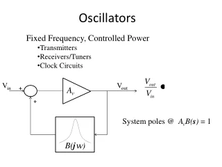
Oscillators circuit analysis. Identifying the open loop gain is a useful technique for oscillator analysis However there are circuits where it is difficult to apply the open loop gain For this reason two additional methods of oscillator design and analysis will be presented

Oscillators circuit analysis
E N D
Presentation Transcript
Oscillators circuit analysis Identifying the open loop gain is a useful technique for oscillator analysis However there are circuits where it is difficult to apply the open loop gain For this reason two additional methods of oscillator design and analysis will be presented These two methods are The direct analysis of the circuit equation The negative resistance concept 1
Circuit analysis The three terminal device could be either a BJT or FET transistor The three external impedances represent feedback connections 2
Circuit analysis The small signal equivalent circuit is given below 3
Circuit analysis The loop equations for the small signal circuit are Note that the voltage v can be determined from the equation below This equation can be rearranged as 4
Circuit analysis The above two equations in matrix form can be rewritten as For the amplifier to oscillate, currents ib and i1 must be nonzero, even when Vi=0, this is only possible when if the system determinant is zero 5
Circuit analysis The above equation can be rearranged as shown below For simplicity only the case when Zi is real value will be considered (i.e. ) The previous equation can be rewritten as 6
Circuit analysis The last equation can be satisfied if Since rπis a positive number, then Or This results shows that Z1 and Z2 must have the same impedance type (ie if Z1 is a capacitor, then Z2 is a capacitor too and Z3must be an inductor) 7
Circuit analysis If Z1 and Z2 are capacitors and Z3 is inductor then the oscillator is referred to as a Colpitts oscillator as shown below 8
Circuit analysis If Z1 and Z2 are capacitors and Z3 is inductor then the oscillator is referred to as a Colpitts oscillator as shown below 9
Circuit analysis If the emitter in the Colpitts oscillator is grounded then the oscillator is known as a Pierece oscillator 10
Circuit analysis In the previous analysis, Z1, Z2, Z3 and Zi were assumed to be ideal (ie the inductor and capacitors have some resistors with them) For example, if in the analysis of Colpitts oscillator Z3 was an inductor with a series resistance Then the system coefficient matrix became as 11
Circuit analysis If we solve the determinant of the above equation and make it equal zero, we got the following two equations 12
Circuit analysis If define the following ratio from the first equation in slide 12 we have 13
Circuit analysis From the previous equations we can see that The second equation in slide 11 can be rewritten as 14
Circuit analysis The resonant frequency can be found from From the previous discussion we can see that the presence of small resistance in series with the inductor will cause a small shift in the resonant frequency 15
Design example Example:Design a 5-MHz Colpitts oscillator using a 10-μH inductor with an unloaded Qu of 100. The transistor β is 100 Solution: From the resonant frequency we have 16
Design example Solution: From the Qu factor of the inductor we have If we assumed that C1=C2=200 pF, then from 17
Design example 2 Example: In the Colpitts oscillator circuit designed in the previous example, what will be the oscillation frequency if the bias current is increased so that rπ =1000 Ω? Solution: The value of can be found from This shows that a mall change in the bias current can change the rπ , and change the oscillation frequency 19
Design example 2 The previous results shows explains the principle of operation of FM modulator (NBFM) 20
Another Interpretation of the oscillator circuit An alternative interpretation of the oscillator presented by Gouriet will presented here The interpretation is based on the fact that, if an ideal tuned circuit, once excited will oscillate indefinitely The reason for the continuous oscillation is that there is no resistive element present to dissipate the energy In the actual case the oscillation will die because the presence of resistive element 21
Another Interpretation of the oscillator circuit It is the function of the amplifier to maintain oscillation by supplying an amount of energy equal to that dissipated This source of energy can be interpreted as a negative resistor ri in series with tuned circuit To maintain oscillationthe following condition must be met 22
Another Interpretation of the oscillator circuit To see how a negative resistance is realized, the input impedance of the following circuit will be derived 23
Another Interpretation of the oscillator circuit The small signal model of the previous circuit is as shown below 24
Another Interpretation of the oscillator circuit The steady state loop equations at the input of the transistor are After Ib is eliminated from these two equations, Zi is obtained 25
Another Interpretation of the oscillator circuit If , the input impedance is approximately equal to but or 26
Another Interpretation of the oscillator circuit It can be seen that the real part of the input impedance is a negative resistance 27
Another Interpretation of the oscillator circuit It can be seen that the real part of the input impedance is a negative resistance The negative resistance is connected in series with an input capacitor If an inductor with finite series resistance r is connected across the input, the circuit will oscillate if the inductor resistance is given by 28
Another Interpretation of the oscillator circuit The frequency of oscillation will be given by Recall that the essential condition for oscillation is that the inductor resistance r is If C1 = C2 = Cm, then 29
Clapp –Gouriet Oscillator The circuit shown below is know as Clapp or Clapp-Gouriet oscillator 30
Clapp –Gouriet Oscillator Clapp oscillator is similar to Colpitts oscillator In Clapp oscillator the oscillation frequency is adjusted by the CO capacitor The oscillation frequency can be determined from the following equation 31