Improving Geometric Accuracy in Cone-Beam Computed Tomography (CBCT) Through Misalignment Correction
This study focuses on enhancing the geometric accuracy of Cone-Beam Computed Tomography (CBCT) systems, addressing misalignment issues through a two-step calibration process. We utilize a 14x14 metal-hole phantom and five pin-hole phantoms for precise adjustment of the X-ray focal spot and accurate geometric alignment between the source and detector. The methodology involves comprehensive 2D projection analysis, aiming to minimize distortion and improve image quality. Results demonstrate significant improvements in calibration effectiveness, informing future advancements in medical imaging systems.

Improving Geometric Accuracy in Cone-Beam Computed Tomography (CBCT) Through Misalignment Correction
E N D
Presentation Transcript
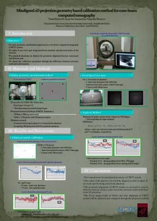
I. Introduction Cone-beam computed tomography (CBCT) system for medical diagnosis • Objectives • To solve geometric problem(misalignment) in cone-beam computed tomography (CBCT) system. • To adjust X-ray focal spot using metal-hole phantom and physical center of the detector. • Five pin-hole phantoms on detector for geometric alignment between source part and detector part. • To obtain the calibration parameters through the difference between reference point and rotation point. Misaligned 2D projection geometry based calibration method for cone-beam computed tomography 1Chang-Woo Seo, 1Bo Kyung Cha,, 1Sungchae Jeon , 1Young Huh , 2Kisung Lee 1Advanced Medical Device Research,, Cent er, Korea Electrotechnology Research Institute, Gyeonggi-do 426-170, Korea 2Department of Radiologic Science , Korea University, S eoul, 136-703, Korea II. Materials and Methods • Gantry geometric measurement method • Focal Spot Correction • 14 x 14 metal-hole phantom • 1.5mm hole diameter with 196 holes • 2mm between hole centers with 0.5mm gap • 5 layers with 10mm layer X-ray source in CBCT Acquired projection in detector • X-ray tube (A-132/B-100, Varian inc.) • Focal spot: 0.6 and 1.2 • Rhenium-tungsten molybdenum target • Flat panel detector (PaxScan 4030CB, Varian inc.) • 397mm x 298mm active area • 2048 x 1536 pixels with 194μm pixel pitch • Phantom research • Correction focal spot using 14 x 14 metal-hole phantom • Acquiring 360 projection with five pin-hole phantom • Analysis Method • Rotation of gantry system from 1 degree to 360 degree • 360 projections in 5rpm rotation • Difference • where r and o are reference point and rotation point of U • and V coordinates, respectively. III. Results and Discussions Gantry distortion measurement(U-axis) • Gantry geometric calibration Position of pin-hole phantom in flat panel detector • 2048 x 1536 pixels • 1.5mm hole diameter with 196 holes • 2mm between hole centers with 0.5mm gap • 5 layers with 10mm layer • Total pattern in each angle • Pin-hole (2,3) : droop problem from 90 to 270 angle • Pin-hole (4,5) : droop problem from starting and 50 angle Gantry distortion measurement(center pin-hole phantom) IV. Conclusions • Two-step process for misaligned geometry of CBCT system. • The center of the detector was forcibly aligned in order to adjust X-ray focal spot by using metal-hole phantom. • The geometric alignment of CBCT system was measured by using the difference between reference point (start point) and each rotation point based on the 2D projection. • The X-ray image results of before and after alignment of CBCT system will be analyzed and compared through the proposed method. • U- and V-axis • U-axis : front-rear direction • V-axis : left-right direction Gantry distortion measurement(V-axis) • Total pattern in each angle • Pin-hole (3) : much distortion after 180 angle • Pin-hole (5) : droop problem from starting and 50 angle