Crystal Physics
Explore the resistance and organization of crystalline and amorphous solids, crystal structures, lattice systems, Bravais lattices, and crystallographic planes in materials science.

Crystal Physics
E N D
Presentation Transcript
Crystal Physics Prepared by S. Sheik Fareed MOHAMED SATHAK ENGINEERING COLLEGE
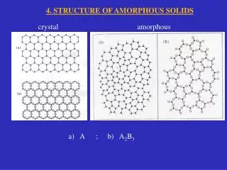
SOLIDS • Solids have “resistance” to changes in both shape and volume • Solids can be Crystalline or Amorphous • Crystals are solids that consist of a periodic array of atoms, ions, or molecules • If this periodicity is preserved over “large” (macroscopic) distances we call it“Long Range Order” • Amorphous solids do not have Long-Range Order • Short Range Order
SOLIDS • Crystals Solids: • Short Range Order • Long Range Order • Amorphous solids: • Short Range Order • No Long-Range Order
Crystals • The periodic array of atoms, ions, or molecules that form the solids is called Crystal Structure • Crystal Structure = Space (Crystal) Lattice + Basis • Space (Crystal) Lattice is a regular periodic arrangement of points in space, and is purely mathematical abstraction • Crystal Structure is formed by “putting” the identical atoms (group of atoms) in the points of the space lattice • This group of atoms is called Basis
Crystals Crystal Structure = Space Lattice + Basis
= between b and c = between c and a a = between a and b b A parallelepiped is generated by the vectors a , b and c 3-D Unit Cell
3-D Unit Cell Different lattice systems are created by varying the lengths a, b and c and the angles , and . • To examine the point symmetry, we look for: • rotation symmetry axes, • reflection planes and • inversion centre. SEVEN systems for 3-D lattices.
1. CUBIC SYSTEM All three sides equal, All three right angles a = b = c = = = 90° • Point symmetry • 90 rotations about three axes, • 120 rotations about four cube diagonals • 180 rotations about six axes • Inversion.
2.TETRAGONAL SYSTEM Two sides equal, All three right angles a = b c = = = 90° Point symmetry 1. 90 rotation about two axis, 2. 180 rotation about one axis, 3. inversion.
3. ORTHORHOMBIC SYSTEM • All three sides different, • All three right angles • Point symmetry • 180 rotations about three • mutually perpendicular axes • 2. Inversion a b c == = 90°
4. MONOCLINIC SYSTEM • All three sides different, • Two right angles, • third arbitrary • Point symmetry • 180 rotation about one axis • Inversion. a b c = = 90°, 90°
a b g 5. TRICLINIC SYSTEM All three sides different All three angles different a b c Point symmetry :Inversion
6. TRIGONAL SYSTEM All three sides equal, All three angles equal, of arbitrary value, a = b = c = = 90° • Point symmetry • 120 rotation about one axis • Inversion
7. HEXAGONAL SYSTEM Two sides equal, third arbitrary, Two right angles, third angle 120 a = b c = = 90°, = 120° • Point symmetry • 60° rotation about one axis • Inversion
BRAVAIS LATTICES. A complete analysis based on mathematics and geometry has shown that a single lattice system can have at the most FOUR types. In all the seven lattice systems have a total of 14 types. These are called theBRAVAIS LATTICES.
Lattice points at the corners of the parallelopiped and at the centre of the faces which intersect c. Unit Cell P type PRIMITIVE LATTICE Lattice points only at the corners of the parallelepiped. BASE CENTRED LATTICE
Unit Cell I type BODY-CENTRED LATTICE Lattice points at the corners of the parallelopiped and at the centre of the each unit cell. FACE- CENTRED LATTICE F type Lattice points at the corners of the parallelepiped and at the centre of each face of the unit cell.
Seven systems divide into 14 Bravais lattices : • Triclinic P • Monoclinic P, C • Orthorhombic P, C, I, F • Trigonal P • Hexagonal P • Tetragonal P, I • Cubic P, I, F
Seven systems divide into 14 Bravais lattices : Notation P: Primitive (lattice points only at the corners of the unit cell) I: Body-centred (lattice points at the corners + one lattice point at the centre of the unit cell) F: Face-centred (lattice points at the corners + lattice points at centres of all faces of the unit cell) C: End-centred or base-centred (lattice points at the corners + two lattice points at the centres of a pair of opposite faces)
Crystallographic Planes • Example: • (hkl) = (123) z y x
Reciprocal 1/2 1/3 1/3 3 a3 a2 a1 3 2 Miller index a1 intercept is 2 a2 intercept is 3 a3 intercept is 3 Hence Miller indices are 3,2,2 and are depicted by ( hkl ) = (322) Calculate reciprocal of these intercepts and reduce them to smallest three integers having same ratio.
√h 2 + k 2 + l 2 a dhkl = Inter-planer Distance (hkl) represent a family of planes. All parallel crystal planes have the same Miller index.These planes are equally spaced at distance dhkl . This distanceis defined as:
a1 a2 a3 (110) dhkl = a/√2 (111) dhkl = a/√3 Crystal planes in a cubic unit cell (100) dhkl = a
c (0,0,1) (0,1,1) h k l ( 0 1 0 ) (1,0,1) (1,1,1) d = a (0,1,0) b (0,0,0) (1,0,0) (1,1,0) a
c (0,0,1) (0,1,1) h k l ( 1 1 0 ) (1,0,1) (1,1,1) d = a/√2 (0,1,0) b (0,0,0) (1,0,0) (1,1,0) a
c (0,0,1) (0,1,1) h k l ( 1 0 1 ) (1,0,1) (1,1,1) d = a/√2 (0,1,0) b (0,0,0) (1,0,0) (1,1,0) a
c (0,0,1) (0,1,1) h k l ( 1 1 1 ) (1,0,1) (1,1,1) d = a/√3 (0,1,0) b (0,0,0) (1,0,0) (1,1,0) a
c (0,0,1) (0,1,1) h k l ( 0 0 2 ) (1,0,1) (1,1,1) d = a/2 (0,1,0) b (0,0,0) (1,0,0) (1,1,0) a
c (0,0,1) (0,1,1) h k l ( 1 1 0 ) (1,0,1) (1,1,1) (,-1 0,0) (0,1,0) (0,0,0) d = a/√2 b (1,0,0) (1,1,0) a
(Simple Primitive Cubic) R = a/2 Co ordination= 6 N = NB+ Nf /2 + Np / 8 = 0 + 0 + 8/8 = 1
(F C C Cubic) √2 a = 4R R = a/2√2 Co ordination= 12 N = NB+ Nf /2 + Np / 8 = 0 + 6/2 + 8/8 = 4
B C C Cubic) (B C C Cubic) √3 a = 4R R = √3 a/4 Co ordination= 8 N = NB+ Nf /2 + Np / 8 = 1 + 0 + 8/8 = 2
Body-Centered Cubic (BCC) • In BCC structure, all atoms are the same element(different colors are used here for visual clarity) • Total of 2 atoms per unit cell: • Coordinates occupied:
Body-Centered Cubic (BCC) • Atomic packing factor • Relationship between atomic radius rand lattice parameter a: • Volume of atoms: • Volume of unit cell: • Atomic packing factor:
Face-Centered Cubic (FCC) • cubic close-packed (CCP) • In FCC structure, all atoms are the same element • Total of 4 atoms per unit cell: • Coordinates occupied:
Face-Centered Cubic (FCC) • Atomic packing factor • Relationship between atomic radius rand lattice parameter a: • Volume of atoms: • Volume of unit cell: • Atomic packing factor:
Hexagonal Close-Packed (HCP) • Total of two atoms per unit cell (shaded) • Net 1 atom at corners • Plus 1 atom inside cell
Hexagonal Close-Packed (HCP) • Atomic packing factor in ideal HCP • Relationship between atomic radius rand lattice parameter a: • Volume of atoms: • Volume of unit cell: — the same as for fcc
FCC STACKING SEQUENCE • ABCABC... Stacking Sequence • 2D Projection • FCC Unit Cell
HEXAGONAL CLOSE-PACKED STRUCTURE (HCP) • ABAB... Stacking Sequence • 3D Projection • 2D Projection Adapted from Fig. 3.3, Callister 6e. • Coordination # = 12 • APF = 0.74
Close-Packed Structures • FCC from stacking of close-packed planes: A B C A B C …
NaCl structure • Since RNa = 1.85 A and RCl = 0.99 A. Their ratio is 0.535 so they are arranged in 6-6 coordination. • Both Na+1 and Cl-1 are arranged in F.C.C structure • The origin is taken as Na (0,0,0) then the F.C.C arrangement for Cl starts at (a/2,0,0) • Examples KCl, LiH, KBr, PbS, MgO etc.
Crystal Structure of Diamond Basis on “left face” atom Basis on “front face” atom Basis on “bottom face” atom Basis on “corner (origin)” atom
CRYSTAL DEFECTS • All atoms are at rest on their correct lattice position. • Metals are not perfect neither at the macro level and nor at the micro level • Contain a number of different types of crystalline defects (at the atomic level) • Vibration of atoms can be regarded as a form of defects. • Defects are important in many processes e.g. diffusion, deformation.
Classification of defects in solids • Zero-dimensional (point) defects • Vacancies, Interstitial atoms (ions), Foreign atoms (ions) • One-dimensional (linear) defects • Edge dislocation, screw dislocation • Two-dimensional (flat) defects • Antiphase boundary, shear plane, low angle twist • boundary, low angle tilt boundary, grain boundary, surface • Three-dimensional (spatial) defects • Pores, foreign inclusions
Vacancy Interstitial Non-ioniccrystals Impurity Substitutional 0D(Point defects) Frenkel defect Ioniccrystals Schottky defect • 0D (point) defects are imperfect point-like regions in the crystal about the size of 1-2 atomic diameters. • The extent of the distortion field may however extend to a larger distance. • Point defects can be created by ‘removal’, ‘addition’ or displacement of an atomic species (atom, ion). • Defect structures in ionic crystals can be more complex and are not discussed in detail in the elementary introduction.
Substitutional Impurity/Element Foreign atom replacing the parent atom in the crystal E.g. Cusitting in the lattice site of FCC-Ni Overlaid to illustrate the relative size of atom and void (usually the insterstitial atom is bigger than the void) Interstitial Compressive & Shear Stress Fields Impurity Or alloying element Compressive stress fields Substitutional Interstitial Impurity/Element Foreign atom sitting in the void of a crystal E.g. C sitting in the octahedral void in HT FCC-Fe Tensile StressFields