Digital Voice Communication Link
This project explores digital voice communication, focusing on the conversion of analog speech signals to digital formats using Differential Pulse Code Modulation (DPCM). The goal is to analyze and implement algorithms in MATLAB to minimize communication bit rates while maintaining acceptable speech quality. By capturing signals via a microphone and compressing them using DPCM, we achieve significant reductions in file size and improved transmission reliability. Results indicate a compression ratio of 4:1, demonstrating the effectiveness of DPCM in audio signal processing.

Digital Voice Communication Link
E N D
Presentation Transcript
Digital Voice Communication Link EE 413 – TEAM 2 April 21st, 2005
Team 2 • Nilesh Malhotra • Abhishek Jaidka • Aditya Mathur
Outline • Overview • Objectives • System Flowchart • Conversion of Analog Speech Signal to Digital • DPCM • FM • Results Achieved • Conclusion
Why Digital Voice Communication Link • Digital communication techniques represents the most straightforward ways for the transmission and perfect reproduction of speech signals. • A big advantage of digital modes is that errors in transmission may be made relatively easy to detect and correct • Digital signals use some advanced processing techniques which achieve performance levels not otherwise possible
Overview • Implement a low bit rate speech Codec & simple Communication protocol • A signal was captured over a microphone and fed into a DPCM compression algorithm to quantize and compress it. • The compressed data stream was then modulated and transferred through a simulated channel. • This data stream was then demodulated and decompressed and the signal was output to a speaker
Objectives • Analysis and Implementation of algorithms in Matlab. • The emphasis is on minimizing the required communication bit rate while maintaining acceptable speech quality. • To obtain an acceptable compression ratio.
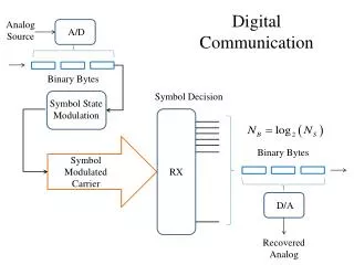
Conversion of analog speech signals to digital The human voice is a continues signal in the range 0-4 KHz. Digital communication on the other hand, is based on discrete bits (0 and 1). Therefore, there is a need for converting the human voice into a stream of bits. • Sampling Rate selection (8 kHz):- To digitize an analog signal such as voice, it first must be sampled; i.e. turned into a series of numerical values • Bit – Rate:- Since an analog signal has an infinite number of amplitude levels, a number of bits (N) is required to give the corresponding quantization
Voice to Digital conversion Figure 2
Sampling The figure shows an analog wave being sampled at a rate much higher than its bandwidth. At (A), an analog signal; at (B) the sampled signal
DPCM • Differential pulse code modulation (DPCM) is a procedure of converting an analog into a digital signal. • DPCM (or coding a difference), is based on the fact that most source signals show significant correlation between successive samples so encoding uses redundancy in sample values which implies lower bit rate.
Advantages of DPCM • A typical example of a signal good for DPCM is an audio signal. • In the case of voice signals, the optimum signal to quantization noise advantage of DPCM over a standard PCM is in the neighborhood of 4-11dB.
Advantages of DPCM • The advantages of DPCM can also be expressed in terms of bit rate. Since from the equation: • 10log10(SNR)o = 1.8 + 6R • 6dB of quantization noise is equivalent to 1 bit per sample. • For a constant signal to quantization noise ratio (Assuming sampling rate of 8 kHz), the use of DPCM may provide a saving of about 8-16 kb/s (i.e. 1 to 2 bits per sample ) compared to the standard PCM.
DPCM - practical uses • In practice, DPCM is usually used with lossy compression techniques, like quantization of differences can be used, which leads to shorter code words. • It has significant quantization noise and only mediocre compression rates can be achieved(4:1).
Results Achieved • UNCOMPRESSED FILE • Samples = 102000 samples at 8bits and 8000Hz • File size = 102000 bytes • COMPRESSED FILE • bits per sample = 2 • Samples = 102000 samples at 2bits and 8000Hz • File size = 25500 bytes • Compression Scheme = Differential Pulse Code Modulation • Compression percentage = 25% • Compression ratio = 4 : 1 • Do you want to hear sounds of the input and the output data (Y/N)? n • So that is enough then? • Do you want to view plots of the data (Y/N) ? y • View input, output, channel or all (I/O/C/A) ? a
FM • With frequency modulation, the modulating signal and the carrier are combined in such a way that causes the carrier FREQUENCY (fc) to vary above and below its normal (idling) frequency. The amplitude of the carrier remains constant as shown in figure below. • As the voltage of the modulating signal increases in the positive direction from A to B, the frequency of the carrier is increased in proportion to the modulating voltage. As the voltage reduces from B to C, the frequency of the carrier decreases until it is back to the original value at C. the modulating voltage increases in the negative direction from C to , hence the carrier frequency decreases to a minimum value at D. It will start increasing again from D to E until it reaches its original value again. Thus in one cycle, the frequency has gone up and down (i.e. above and below the idling frequency) as mentioned earlier.
FM cont • Throughout this process the amplitude of the carrier is not affected. The carrier frequency change above and below that of the un modulated condition is proportional to sign and amplitude of the modulating signal.
Conclusion • In this presentation, a model for a Digital Voice Communication Link has been presented. The system consists of four main stages. The function of each stage was verified and its relation to the other parts of the system was identified.
Timeline • Group Formation 25 Jan • Decided on Topic 5 Feb • Literature Search 20 Feb • Design & Discussion 1 March • Coding 2 March • Mid Term Presentation 8 March • Coding continued • Lab Demonstration 7 April • Final Presentation 21 April