
Chap. 6 Digital Arithmetic: Operations & Circuits
Chap. 6 Digital Arithmetic: Operations & Circuits. Introduction This chapter will be concentrate on how computers perform the basic arithmetic operations 6-1 Binary Addition Addition is the most important operation in digital systems

Chap. 6 Digital Arithmetic: Operations & Circuits
E N D
Presentation Transcript
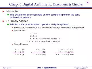
Chap. 6 Digital Arithmetic: Operations & Circuits • Introduction • This chapter will be concentrate on how computers perform the basic arithmetic operations • 6-1 Binary Addition • Addition is the most important operation in digital systems • Subtraction, multiplication and division are usually implemented using addition. • Basic Rules : 0 + 0 = 0 1 + 0 = 1 1 + 1 = 10 = carry of next position + 0 1 + 1 + 1 = 11 = carry of next position + 1 • Binary Example : 0 1 1 (3) 1 0 0 1 (9) 1 1. 0 1 1 (3.375) + 1 1 0 (6) + 1 1 1 1 (15) + 1 0. 1 1 0 (2.750) 1 0 0 1 (9) 1 1 0 0 0 (24) 1 1 0. 0 0 1 (6.125)
6-2 Representing signed Numbers • Sign Bit • 0 : positive, 1 : negative • Sign-magnitude system • Example : 5210 (decimal) = 1101002 (binary) + 5210 = 01101002 (sign-magnitude) - 5210 = 11101002 (sign-magnitude) • This is simple, but is normally not used, as it makes circuit implementation more complex • 1’s Complement Form • Example : 101101(original binary number) 010010(1’s complement) • Change each bit in the number to its complement • 2’s Complement Form • Example : 4510 (decimal) = 1011012 (binary) + 4510 = 01011012 (true binary) - 4510 = 10100112 (2’s complement)= 1010010(1’s complement) + 1 • Take the 1’s complement and add 1 to the LSB position +14 -14 0 0001110 1 0001110 0 0001110 1 1110001 0 0001110 1 1110010 1) Sign magnitude system 2) 1’s complement system 3) 2’s complement system
Representing signed Numbers Using 2’s Complement : Fig. 6-2 • If number is positive • Magnitude = true binary form, Sign = 0 is placed in front of the MSB • If number is negative • Magnitude = 2’s complement form, Sign = 1 is placed in front of the MSB • 2’s complement is the most commonly used system for representing signed binary numbers • Perform the operation of subtraction by actually performing addition • A digital computer can use the same circuitry to both add and subtract(saving in hardware) • Negation • The operation of converting a positive number to its negative equivalent or a negative number to its positive equivalent • 0 1 0 0 1 = + 9 Start with • 1 0 1 1 1 = - 9 Negate(2’s complement) • 0 1 0 0 1 = + 9 Negate again(2’s complement) • We negate a signed binary number by 2’s complementing it Sign 과 Magnitude를 동시에 2’s 보수 취하는 것과 동일함
Special Case in 2’s Complement Representation : Tab. 6-1 • Smallest number(using N magnitude bits) • 1 followed by N zeros : 1000 = - 8 ( -2N ) • Largest number(using N magnitude bits) • 0 followed by N ones : 0111 = +7 ( 2N -1 ) • 6-3 2’s Complement Addition • Addition Rules • 1) Simply add the two signed 2’s complement numbers • 2) Disregard any carry from the sign bit. • Examples : • 9 + 4 = 01001 + 00100 = 01101 • 9 + ( -4 ) = 01001 + 11100 = 1 00101 • ( -9 ) + 4 = 10111 + 00100 = 11011 • ( -9 ) + ( -4 ) = 10111 + 11100 = 1 10011 • 9 + ( -9 ) = 01001 + 10111 = 1 00000 Discard Carry
6-4 2’s Complement Subtraction • Subtraction Rules • 1) Negate the subtrahend • 2) Add this to the minuend • 3) Discard carry • Examples : • 9 - 4 = 9 + ( - 4 ) = 01001 + 11100 • ( - 9 ) - 4 = ( - 9 ) + ( - 4 ) = 10111 + 11100 • 9 - 9 = 9 + ( - 9 ) = 01001 + 10111 • Arithmetic Overflow • Overflow Condition • Two positive or two negative numbers are being added • Overflow Detection • Detected by observing the carry into the sign bit position and the carry out of the sign bit position • If these two carries are not equal, an overflow condition is produced (Exclusive-OR gate = 1) * Overflow Exam) out inout in carries 0 1 carries 1 0 + 70 0 1000110 - 70 1 0111010 + 80 0 1010000 - 80 1 0110000 + 150 1 0010110 - 150 0 1101010
6-5/6-6 Binary Multiplication/Division • Use the same procedures as for decimal multiplication and division • Exam) • 6-7 BCD Addition • BCD Addition Procedure • 1) Add the BCD code by using ordinary binary addition • 2) The sum is 9 or less, no correction is needed • 3) The sum is greater than 9, the 0110(6) should be added Multiplication: Division: 1 0 0 1 0 0 1 1 1 0 1 1 1 1 1 0 0 1 1 0 0 1 0 1 1 1 0 0 1 0 0 1 1 0 0 0 0 0 1 1 1 0 0 1 0 1 1 0 0 0 1 1 shift and add! shift and subtract! 0 1 1 0 BCD for 6 + 0 1 1 1 BCD for 7 1 1 0 1 invalid sum 0 1 1 0 add 6 for correction 0 0 0 1 0 0 1 1 BCD for 13
6-8 Hexadecimal Arithmetic • Hex Addition : Exam. 6-6, 6-7, 6-8 • Hex Subtraction : Exam. 6-9 • 1) The 2’s complement of the subtrahend will be taken, then added to the minuend • 2) Any carry out of the MSD position will be disregarded • Hex Representation of Signed Number : Tab. 6-2 • Computer Numbering System = 2’s Complement System • 6-9 Arithmetic Circuits • ALU(Arithmetic/Logic Unit) : Fig. 6-3 • All arithmetic operation take place in the ALU of a computer • The purpose of the ALU : • 1) Accept binary data that are stored in the memory • 2) Execute arithmetic and logic operations on these data (according to instruction from the control unit) • ALU contains at least two flip/flop registers : Accumulator(ACC or A), B register • A : Operand 1 저장(중간 또는 최종 연산 결과 저장) • B : Operand 2 저장
A typical sequence of operation : A+Bregister • 1) Control Unit은 명령어에 명시된 Operand 주소에 따라 메모리 번지를 지정한다. • 2) 메모리로 부터 Operand 데이터를 B register로 전송 • 3) A 와 B 를 더한 후, 그 결과를 A에 저장 • 4) A는 다른 Operand와 다시 더해질 수 있으며, 또는 메모리에 저장될 수 있다. • 6-10 Parallel Binary Adder • Typical binary addition : Fig. 6-4 • Augend : A, Addend : B register • Parallel Adder : Fig. 6-5 • The augend and addend are fed to a full adder(Sec. 6-11) • The additions in each bit are taking place at the same time • 6-11 Design of a Full Adder • Truth Table for a Full Adder : Fig. 6-6 • Complete Circuitry for a Full Adder : Fig. 6-7 • K-Map Simplification : Fig. 6-8 Full Adder : 3 inputs Half Adder : 2 inputs
6-12 Complete Parallel Adder with Registers : Fig. 6-9 • Sequence of Operations : Exam) 1001(A) + 0101(B) • t1 : CLEAR (A = 0000) • t2 : LOAD (B= 1001) • t3 : TRANSFER (A= 1001) • t4 : LOAD (B= 0101) • t5 : TRANSFER (A= 1110) • Register Notation • The contents of register A : • The contents of the B register is transferred to the A register : • the A register will be changed, and the B register will be unchanged • 6-13 Carry Propagation • Carry Propagation = Carry Ripple • The speed of parallel adder(Fig. 6-9) is limited by an effects called carry propagation or carry ripple • Last position(MSB) will not reach its final value until after n FF propagation delays (for n bit adder) • A scheme for reducing this delay : Look-ahead Carry • Utilize logic gates to look at the lower-order bits of the augend and addend(to see if a higher-order carry is to be generated) • Many IC adders use look-ahead carry 0000(A)+ 1001(B) 1001(A) + 0101(B) Carry Propagation is solved by more hardware circuitry
6-14 IC Parallel Adder • 7483/74283 : Fig. 6-10(a) • Cascading Parallel Adders : Fig. 6-10(b) • Exam. 6-10)Determine the inputs/outputs when 72 is added to 137 in Fig. 6-10 • 6-15 2’s Complement System • Addition : Fig. 6-11 • +6 ( 0110 ) + -3 ( 1101 ) = +3 ( 0011 ) • Subtraction : Fig. 6-12 • 4 ( 0100 ) - 6 ( 0110 ) = 4 ( 0100 ) + -6 (2’s complement of +6) = 0100 + 1001(1’s complement of +6) + 1(Co) = 1110 ( -2 ) • Combined Addition and Subtraction : Fig. 6-13 • ADD = 1, SUB = 0 • Enable : AND gate 1,3,5,7 Disable : AND gate 2,4,6,8 • ADD = 0, SUB = 1 • Enable : AND gate 2,4,6,8 Disable : AND gate 1,3,5,7 Co = 1 * 차이점 83 : GND= 12 , Vcc= 5 283 : GND= 8 , Vcc= 16 B 입력
6-16 BCD Adder • Same as Sec. 6-7 : Fig. 6-14 • X will be HIGH for either of the following conditions : Tab. 6-3 • Whenever S4 = 1(sums greater than 15) • Whenever S3 = 1 and either S2 or S1 or both are 1(sums 10 to 15) X = S4 + S3(S2 + S1) • Cascading BCD Adder : Fig. 6-15 • 6-17 ALU IC • 74382 : Fig. 6-16 • Exam. 6-12 • Expanding the ALU : Fig. 6-17 • Exam. 6-13 • Other ALU : 74181 • 16 operations : We must add the correction 0110
6-19 Troubleshooting Case Study • Test Results • Mode 1 : ADD = 0, SUB = 0 • Result : Sum = A + 1 ( 정상 : Sum = A ) • Mode 2 : ADD = 1, SUB = 0 • Result : Sum = A + B + 1 ( 정상 : Sum = A + B ) • Mode 3 : ADD = 0, SUB = 1 • Result : Sum = A - B ( 이상 없음 ) • Possible Faults • 1) LSB 가 항상 1 : Mode 3에서 정상임으로 배제 • 2) Co = 1 : SUB와 Co 사이에 Open = HIGH Input = 1 • Exam. 6-14)Describe the effects of a break in betweenSUBandAND(X) in Fig. 6-19 • Mode 1 : A + B • Mode 2 : A + B + B = A + 1111 = A - 1 • Mode 3 : A - B, 이상 없음 1 OR 0 = 1 0 OR 1 = 1
6-20 PLD Full Adder • Exam. 6-15)”SET” operation example. • 4 bit Full Adder Source file : Fig. 6-20 p. 286 Equ. (6-3) p. 286 Equ. (6-2)