Download
1 / 29
300 likes | 483 Vues
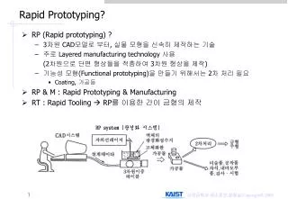
Software Error Compensation of Rapid Prototyping (RP). Kun Tong, Sanjay Joshi, Amine Lehtihet Department of Industrial and Manufacturing Engineering The Penn State University DIMACS CAD/CAM Workshop Rutgers University, October 8, 2003. Rapid Prototyping (RP).

E N D
Software Error Compensation of Rapid Prototyping (RP) Kun Tong, Sanjay Joshi, Amine Lehtihet Department of Industrial and Manufacturing Engineering The Penn State University DIMACS CAD/CAM Workshop Rutgers University, October 8, 2003
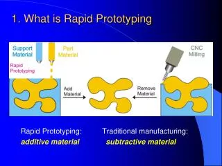
Rapid Prototyping (RP) • A fabrication method in which parts are built by depositing material layer by layer under computer control. CAD Model Slices Stereolithography Apparatus (SLA) STL file (A triangular approximation of the 3D surface geometry.)
Dimensional Accuracy Dimensional Accuracy: • SLA 250 machine: 0.002 inch/inch (Lynn (2000)) • FDM 3000 machine: “Overall tolerance is ± 0.005 inch in the X, Y, and Z axes.” Main Error Sources in RP Processes: • Positioning error of the tool tips (the laser beam focus or the depositing nozzle) • Material shrinkage/expansion due to physical or chemical changes during prototyping • CAD model STL file approximation error • Staircase Effect due to finite layer thickness • …
Accuracy Studies for RP • Focused on different aspects of process planning for RP • STL File Correction Algorithms (van Niekerk (2000)) • Slicing Algorithms(Kulkarni (1996), Tata (1998)) • Tool Path Planning(Wah (2001)) • Support Structure Generation Methods • Parametric Tuning (Lynn(1999), Onuh(2000), Zhou(2000)) • Build Orientation Optimization(Alexander(1998), Nee(2001)…) • Limitation: The best-tuned system still has considerable systematic error.
Volumetric Error dx dy dz z y x Software Error Compensation • Error Compensation: To cancel the effect of an error without removing the error source. • Very little work has been done on error compensation of RP. Nominal Position (x, y, z) Actual Position (x+dx, y+dy, z+dz) Compensated Input (x-dx, y-dy, z-dz) RP working envelope
Software Error Compensation Approach • This concept has been applied to Coordinate Measuring Machines (CMM) and machine tool systems. • Three-step procedure: • Build a Mathematical Machine Error Model—to write the components of the volumetric error (dx, dy, dz) as functions of the coordinates x, y and z. • Develop a method of measurement to determine the coefficients in the model. • Implement the error model in the machine control for compensation.
How to Build the RP Error Model? • Mechanistic Model or Statistical Model? • RP machine is a complex system. It is very hard, if not impossible, to build a mechanistic model. • Statistical model will introduce a lot of predictors which might not be significant and have no physical meaning. • Solution: Build an approximated mechanistic model using the Parametric Errors Functions and Rigid Body Kinematics as used for Coordinate Measuring Machines or Machine Tool Systems.
Coordinate Measuring Machine (CMM) Y Z X Actual Nominal CMM
18 Parametric Errors (Geometric Errors) • The 6 parametric errors of each axis are only functions of the coordinates in that axis.
CMM Machine Error Model • Using Rigid Body Kinematics and Homogeneous Transfer Matrix, we can write the machine error model: • (x, y, z): nominal position • (Xp, Yp, Zp): actual position of the probe tx ty tz are the tool tip offset are unrepeatable errors.
RP “virtual” Parametric Errors • Besides the geometric errors of the three axes, material volume change during prototyping is also a major error source. • Assumption: all errors in the RP process can be mapped into the 18 “virtual” parametric errors. Then rigid body kinematics is used to write the error model. • SLA 250 machine error model: 14 “virtual” parametric errors show up in the model.
Polynomial Parametric Error Functions • 3rd order Legendre Polynomials are used to approximate the parametric error functions.For example: • Totally, 143=42 unknown coefficients need to be determined for the error model of SLA machine.
Estimate the Coefficients Using Artifact • A LINGO program is written to minimize the sum of squares of the residual errors: • 169 cylinders: 8 inch (X) 8 inch (Y) 3.5 inch (Z)
Volumetric Error Map of SLA 250 at a Fixed Z Height (Z = 1 inch)
Software Error Compensation • CAD model STL File Slice File RP Machine Control File Apply Compensation to all the vertices in STL file
Compensation Test Part Apply compensation to a test part with 49 cylinders of same diameter but at different locations from those in the 3D artifact.
Volumetric Errors Reduction by Software Error Compensation Before Compensation After Compensation On average, volumetric errors are reduced to 35% of their original values.
-0.0020-0.0003 -0.00360.0011 0.00190.0032
Summary of Compensation Results • The overall size and the feature positions on the part are considerably improved. • Dimensions involving height in z direction such as depth of holes, or with the presence of staircase effect such as the sphere size, are not improved and in some cases may get worse. (Z quantization) • Cylindrical holes sizes are improved by a small amount and both uncompensated and compensated sizes are consistently smaller than their nominal values. (Triangulation Error)
“Z value quantization”—in Uncompensated Parts Uncompensated Model Model Top Surface Slicing Planes Actual Surface
“Z value quantization”—in Compensated Parts Compensated Model Multiple Layers Model Top Surface Slicing Planes Actual Surface
Eliminate Multiple Layers Phenomenon • Algorithm: • Identify horizontal surfaces in the uncompensated part; • Apply z direction compensation to the vertices of each horizontal surface; • Average the z-coordinates of all vertices on a given horizontal surface and then move the entire horizontal surface up or down to the nearest adjacent layer. • Move corresponding vertices in the entire STL files to maintain connectivity.
Summary • Software error compensation can help RP users to achieve higher part accuracy without any hardware modification. • “Virtual” parametric error functions include all repeatable error sources present in the rapid prototyping process and can be thought of as a comprehensive evaluation criterion of RP machine accuracy.
Apply Compensation Slice 1 Apply Compensation Slice i Slice N Future Work(1)— Slice File Compensation
Future Work(2)— Design Problem of the 3D Artifact How to choose the cylinder heights is an Design of Experiment (DOE) problem.
Design Criterion • D-criterion • A D-optimal design is one in which the determinant of the moment matrix is maximized: where X is the regression model matrix. N is the sample number. p is the number of coefficients. • Geometrically, with D-criterion, one tries to minimize the volume of the confidence region on the regression coefficient. • Objective: Keep the same X and Y positions of the cylinders, to optimize the distribution of their heights.