Collimator Setup MD
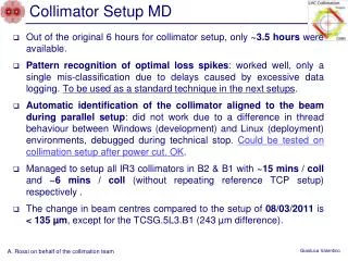
Collimator Setup MD. A. Rossi on behalf of the collimation team. Out of the original 6 hours for collimator setup, only ~3.5 hours were available.

Collimator Setup MD
E N D
Presentation Transcript
Collimator Setup MD A. Rossi on behalf of the collimation team • Out of the original 6 hours for collimator setup, only ~3.5 hours were available. • Pattern recognition of optimal loss spikes: worked well, only a single mis-classification due to delays caused by excessive data logging. To be used as a standard technique in the next setups. • Automatic identification of the collimator aligned to the beam during parallel setup: did not work due to a difference in thread behaviour between Windows (development) and Linux (deployment) environments, debugged during technical stop. Could be tested on collimation setup after power cut. OK. • Managed to setup all IR3 collimators in B2 & B1 with ~15 mins / coll and ~6 mins / coll (without repeating reference TCP setup) respectively . • The change in beam centres compared to the setup of 08/03/2011 is < 135 µm, except for the TCSG.5L3.B1 (243 µm difference).
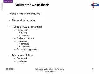
IR3 combined cleaning MD • Scope: Test cleaning efficiency when using IR3 for both momentum and betatron cleaning. • IR3 combined cleaning could be adopted if required for R2E. • Could reduce setup time. • Would reduce impedance. • Measurements performed: • Loss maps on horizontal plane, 3.5TeV with 1 nominal bunch, injection optics . • V collimators in IR7 left in since no vertical collimators in IR3. • Momentum loss maps could not be performed: beam dumped due to unmask-able BLM.
Results for IR3 combined cleaning, H, injection optics ~1e-1 Setup apertures • TCP3 (H) 5.7 s • TCS3 (H,S) 6.7 s • TCLA3 (H,V) 10 s • TCP7 (H,S) 18 s • TCS7 (H,S) 21 s • TCLA7 (H,S) 24 s • TCP7 (V) 5.7 s • TCS7 (V) 8.5 s • TCLA7 (V) 17.7 s • TCT (H,V) 26 s • TCL, TCLI, TDI open B2 ~2e-2 ~1e-2 ~1e-2 • Main losses on TCP.6R3.B2 and TCSG.A5L3.B2 → Hierarchy or showers? (TCP3 was tested to be the primary collimator prior measurements) • High losses at TCTVs right of IR1 (~1%) and IR8 (~2.6%)
SixTrack simulations with collimators as thought to be • TCP3 (H) 5.7 s • TCS3 (H,S) 6.7 s • TCLA3 (H,V) 10 s • TCP7 (H,S) 18 s • TCS7 (H,S) 21 s • TCLA7 (H,S) 24 s • TCP7 (V) 5.7 s • TCS7 (V) 8.5 s • TCLA7 (V) 17.7 s • TCT (H,V) 26 s • TCL, TCLI, TDI open B2 SixTrack simulations with H sheet beam hitting TCP3: cannot reproduce IR3 loss shapes, nor high losses in IR1/8, nor IR6 and IR7 level
SixTrack simulations • TCP3 (H) 5.7 s • TCSG.A5L3.B2 5.7 s • TCS3 (H,S) 6.7 s • TCLA3 (H,V) 10 s • TCP7 (H,S) 18 s • TCS7 (H,S) 21 s • TCLA7 (H,S) 24 s • TCP7 (V) 5.7 s • TCS7 (V) 8.5 s • TCLA7 (V) 17.7 s • TCT (H,V) 26 s • TCL, TCLI, TDI open ~1e-1 Sum of results: sheet beam hitting TCP.6R3.B2 and TCSG.A5L3.B2
Summary and future work • Results: • After standard beam based setup in IR3. • H betatron loss maps dumped both beams. • Measured loss map pattern different from usual: • Main losses on TCP.6R3.B2 and TCSG.A5L3.B2 → Hierarchy or showers? But prior measurements TCP3 was moved in to verify it was the primary collimator. • High losses at TCTVs right of IR1 (~1%) and IR8 (~2.6%) • Simulated loss map pattern could partly be reproduced by overlapping results from “hierarchy breakdown” and sheet beam hitting both collimators with highest losses. • Further study to interpret/reproduce data. • After analysis (simulations also with FLUKA to include showers) measurements should be repeated to validate scheme.
IR3 combined betatron / momentum cleaning TCSM.A5R3.B1 TCSM.B5R3.B1 TCHSH.6L3.B1 TCSM.5L3.B1 TCSM.4R3.B1 TCP. A6L3.B1 TCSG.A5L3.B1 TCSG.B4R3.B1 TCSG.D5R3.B1 TCSG.C5R3.B1 TCP.6L3.B1 TCSG. 5L3.B1 TCSG.4R3.B1 TCSG.A5R3.B1 TCSG.B5R3.B1 Beam 1 Symmetric for Beam 2 TCLA.7L3.B2 TCLA.6L3.B2 TCLA.B5L3.B2 TCSG.4L3.B2 TCSG.5R3.B2 TCP.6R3.B2 TCSG.A5L3.B2 TCLA.A5L3.B2 TCSG.B5L3.B2 Beam 2 • What we would have (+ TCLA’s) • What we could test (no vertical collimators in IR3) 10 s 6.7 s 5.7 s • Less passive absorber than in IR7