Collimator Controls
Collimator Controls. Readiness of collimators control – from bottom to top State of automated collimator positioning Extended LTC Session 6 - Readiness of Controls Friday 07 March 2008 14h30. Collimator Controls. Primary Actors (from bottom – to top)

Collimator Controls
E N D
Presentation Transcript
Collimator Controls Readiness of collimators control – from bottom to top State of automated collimator positioning Extended LTC Session 6 - Readiness of Controls Friday 07 March 2008 14h30
Collimator Controls Primary Actors(from bottom – to top) • Alessandro Masi, Mathieu Donze, Arnaud Brielmann, Jerome Lendaro, Roberto Losito • Jacky Brahy, Enrique Blanco Vinuela • Guy Surback, Roland Chery, Nicolas Zaganidis • Stefano Redaelli, Eric Veyrunes, Delphine Jacquet Support from LSA team, AB/CO-DM, M.Lamont
Outline Installation status Architecture evolution Functional Status • Environmental Survey • Positioning & Survey • Application Layer Automatic Collimator Positioning (Beam Based Optimisation)
Baseline Architecture (as decided in 2005) Data Base Controls Network Central Collimation Application Actual Machine Parameters Ethernet Data Base Machine Timing Critical Settings Machine Timing Distribution Synchronisation Fan out Local Ethernet Segment Motor Drive Control Position Readout and Survey Environment Survey PXI PXI PLC Beam Permit . . . Collimator Supervisory System (one or two per LHC point) Control room OP Control room software: • Management of settings (LSA) • Preparation for ramp • Assistance in collimator tuning • Based on standard LSA components • Dedicated graphical interface for collimator control and tuning • OP responsibility Collimator Supervisor System (CSS): • Environmental Supervision through standard PVSS class • Support building, VME / FESA • Fesa Gateway to Control Room Software • Synchronization of movements • Beam Based Alignment primitives • Takes action on position errors (FB) • Receives timing, send sync signals over fiber to low level (Ramp & Beam Based Alignment) • Synchronization and communication (udp) with BLM • CO responsibility Low level control systems • 3 distinct systems • Motor drive PXI • Position readout and survey PXI • Environment Survey PLC • ATB responsibility& CO for Environment Surface support building BLM system CO Underground, low radiation area ATB CO ATB LHC tunnel
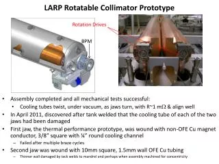
HW Installation status Today some 75 Collimators are installed. == 92 by April ! Details in talk of O.Aberle
HW Installation status Temperature readout • All PLC’s in place • All installed collimators connected • All temperature gauges tested except in IP7 • Very few surprises • IP7: waiting for 220V power connections
HW Installation status PXI installation • All PXI systems installed • Test in progress: stages • Pre-Commissioning • Test signal connectivity • No motor movement • All done (IP7 finished yesterday) • Commissioning 1 • Requires tunnel access for visual confirmation of mechanical movements, swichtches etc. • IP5, IP6 in progress, followed by IP2, IP8, IP1 (constrained by tunnel access), then IP3, IP7. • First LVDT-Calibration • Commissioning 2 • Remote tests • Including PC-gateway & synch-signal • LVDT-reCalibration, autoretraction, mechanical play • Finished by last week of May
HW Installation status CSS related hardware • PC Gateways installed in all points except BA7 • Fibers connectivity for synchronisation signals: • Ready in IP1, IP2, IP3, IP6, IP7 • IP8, IP5 before end of March
Temperature monitoring Based on standard UNICOS / PVSS control environment PLC programs automatically generated from excel files (excel files are extracted from Collimation Configuration tables in the DB with additional dump and alarm limits per temperature sensor • PLC supervised by standard PVSS server • Internal store (Months of data) • Feeds various clients (LoggingDb, Alarm, JapC, Configurable PVSS clients,) PVSS Client PVSS Client Collimation Configuration Japc Clients Japc Clients Japc Clients Japc Clients PVSS Server Alarm System Logging DB PLC PLC PLC
Temperature monitoring Configurable PVSS clients
Architecture Evolution Data Base Data Base Controls Network Controls Network Central Collimation Application Central Collimation Application Actual Machine Parameters Actual Machine Parameters Ethernet Ethernet Data Base Data Base Machine Timing Machine Timing Critical Settings Critical Settings Machine Timing Distribution Machine Timing Distribution Synchronisation Fan out Local Ethernet Segment Motor Drive Control Motor Drive Control PXI PXI Beam Permit Beam Permit Collimator Supervisory System (one or two per LHC point) Collimator Supervisory System (one or two per LHC point) Low Level Fesa (one or two per LHC point) Only considering Position control: 3 Layers For various reasons (responsibility delimitation) the architecture grew more complex with 4 layers. A low level Fesa Server was introduced • Longer Execution Path • More resources, more maintenance • Duplicated functionality • For not much benefit • And a complication for MCS Low Level Fesa Server taking more and more responsibility (calibration, expert access, …) What is the solution ? Make Low Level Fesa Server to implement the same property interface as CSS Suggest to include also synchronisation control in the Low Level Fesa Server. Position Readout and Survey Synchronisation PXI Low Level Fesa CSS Fan out Local Ethernet Segment Position Readout and Survey PXI
Architecture (as evolved after 2007 runs) Data Base Controls Network Central Collimation Application Actual Machine Parameters Ethernet Data Base Critical Settings Motor Drive Control PXI Beam Permit ATB kindly agreed to include the synchronisation control in the Low Level Fesa Low Level Fesa Server became de facto the CSS Central Collimator Application can (almost) talk directly to ATB CSS implementation as if it was the CO CSS implementation Many thanks to A.Masi for this 2007 Christmas present. Machine Timing Collimator Supervisory System (one or two per LHC point) ATB Machine Timing Distribution Synchronisation Fan out Local Ethernet Segment Position Readout and Survey PXI
Architecture (to be completed in 2008) Data Base Controls Network Central Collimation Application Actual Machine Parameters Ethernet Data Base Critical Settings Motor Drive Control PXI Beam Permit Optimisation Application ATB kindly agreed to include the synchronisation control in the Low Level Fesa Low Level Fesa Server became de facto the CSS Central Collimator Application can (almost) talk directly to ATB CSS implementation as if it was the CO CSS implementation Missing functionality • CSS is now reporting asynchronously to requests. (i.e. more work for Stefano). • Beam Based optimisation primitives not provided Need an independent process that runs on the PC gateway Machine Timing BLM system Beam Based Optimisation (one or two per LHC point) Collimator Supervisory System (one or two per LHC point) Machine Timing Distribution Synchronisation Fan out Local Ethernet Segment Position Readout and Survey PXI
PXI and CSS All functionality defined and ~implemented on PXI(except multi movement option for fast optimisation) Merge of Fesa Servers • Expert application for LVDT-Calibration • Interacts with Fesa Server to calibrate • Calibration stored in MCS • Updates under control of RBAC • Fesa device delivery tool • Takes information from • Collimation Configuration DB • PXI configuration DB • Feed Fesa Configuration DB
PXI: Tracking Jaw Positions 50 mm 20 s 50 mm 20 s Setting 10 mm 20 s Reading Setting Reading Generally excellent resolution and performance. In the tunnel at some locations pickup noise. Being analyzed. S. Redaelli
PXI and CSS To be finalized and tested Function driven execution Machine protection functionality • Warning and Dump limits • Machine Protection limits (MCS) depending on Energy Synchronisation Reception of Energy and other Machine Parameters Interaction with applications layer (trim and Sequencer) New functionality to be commisioned in April. • Actual priority is HW commissioning in the tunnel.
Application Layer Stefano has provided a lot of work in collaboration with Eric and Delphine Database Table definitions to store collimator configuration • WEB interface • Collimator configuration database population Collimator Control Application Definition of parameter space to control collimators settings and limits. Adaptation of trim editor (with CO/AP) to visualize more conveniently the collimators following the Beam-IP-family hierarchy
Collimator Parameter Space • High level Trim parameter is expressed in Ns • Absolute values are obtained by folding in the beam based sbeam Xbeam • sbeamis obtained from Momentum, ebeam and bcoll. • ebeam is the nominal emmittance for which the machine is protected. It is a collimator specific parameter. Measured emust be < ebeam • bcoll can be trimmed based on beam based alignment, to correct for local b-beating • Same hierachy for warning and dump limits.
Automated Collimator Positioning by Chiara Bracco • 94 (up to 160 in final upgrade) collimators, to protect against machine damage and magnet quenches. • The collimation process is a multi-staged process that require precise (0.1 beam) setting of the jaws with respect to the beam envelope.Goal for positioning accuracy is 20 m (0.1 beam at 7 TeV). • Actual beam envelope (position and size) may change (from fill to fill ?, by how much?) Adapt to changing beam parameters to guarantee machine protection and to keep good cleaning efficiency • There are 376 degrees of freedom (4 motors per collimator) (188 if not considering the angle of the jaws) 30 seconds per degree of freedom (a very efficient operator) still requires about 3 hours. We need automated tools and procedures 12 minutes for two positions
Beam Probing • Traditional method to establish the beam position, angle and size by touching the actual beam. (Required with new optics or after substantial changes of beam parameters) • Starts with producing a well-defined cut-off in the beam distribution. • Each collimator jaw is moved until the beam edge is touched. This step defines an absolute reference position for each jaw. (and angle if two motors are moved independently) Beam Loss Monitor Beam Loss Monitor • Note: Best done from the last element in the cleaning insertion to the first • Collimators may stay in place • Machine is better protected against quenches • Disadvantages: • Only possible with low intensity beam (i.e. 5 bunches, extrapolation from 5 to 3000 ??). • Slow if done manually (188 positions ) • Delicate (e.g. moving a collimator too far changes the cut-off in the beam distribution).
Fast beam based setup • Complements the traditional set-up method (possible with nominal beam intensity). • Adjust positions to reproduce known beam loss pattern. • Based on experience of other accelerators:Collimation efficiency is more closely related to beam loss patterns than to absolute collimator positions, which are sensitive to orbit deviations, beta beat, etc. • Move jaws in hierarchical order into the beam halo up to the point where a specified beam loss level is recorded in the adjacent beam loss monitors. Beam Loss Monitor Beam Loss Monitor • Fast if implemented as an automated procedure: • Start at a fixed offset relative to a previously known position (only have to move short distances, no need to be retracted. • Two beam can be tuned in parallel in the two cleaning insertions IR3 and IR7
Fast beam based setup Procedure in practice: • The collimators are set at 1.5 σ retracted with respect to the last optimised value. • The jaws are optimised one by one in a precise order. • Optimization by moving in steps of 0.05 σ until the associated set of Beam Loss Monitors (BLM) detects a predefined value of beam loss.The BLM reference levels are found empirically and may be updated from fill to fill. Timing implications: • Starting position –1.5 σ, step size of 0.05 σ (50 μm @ 450 GeV) ⇒ 30 steps/motor ⇒ 9600 steps in total (only position, no angles, final upgrade). Available time 5 min. two rings in parallel ⇒ 60 ms per step (16 Hz) @ 2mm/s 50 μm ⇒ 25 ms per step needed for motor movement => 35 ms for driving, data collection, reading BLM, deciding
BLM system Synchronisation Fan out Local Ethernet Segment Motor Drive Control Position Readout and Survey PXI PXI Collimator Supervisory System (one or two per LHC point) Fast Optimisation Primitives • Collimator Supervisory System(CSS) • Send a trigger to adjacent BLM system on every motor movement • BLM system sends a short “transient” data to the CSS • Optimization primitive command (on CSS) • Move until BLM-level • Parameters • Motors and step size • BLM signals and limits • Repetition frequency • Maximum steps • Example: • Move Jaw-left in steps of 10 um every 30 ms until BL signal reaches 103 • This optimization primitive can be used by a central application for • Beam Probing • Fast beam based optimization Beam Loss Monitor
The real chalenge Motor movement 10ms (20m) Motor movement 50ms (25m) (70 Hz) 12 sec Loss tails with echo During the SPS MD, not able to make clean cut in the beam distribution Beam-dynamics: Re-poppulatution of tails over several 100th of ms. Long tails after collimator movement, Large noise components 50, 150, 300, 450 & 600 Hz noise If these effect are also present in the LHC, optimisation will me more challenging.
Fast Optimisation Implementation To be developed this year. • Implement Multi-Step movements at Low Level • Development of Optimiser Process • Beam Based Optimisation Primitive • Already useful for operator assisted collimator setup. • Development of Central Optimisation Control Process • Sequencing the optimisation of the individual jaw positions • Driven by a DB configuration, able to react intelligently if there is unexpected behaviour. • Initially simple, improve by learning. Doctoral student ? The challenges • Convince BI/SW that transfer of 600 bytes @ 30Hz is sustainable (when used occasionally for a single BLM crate at the time). • Understanding the beam loss response
Conclusions Collimation controls is ready to set the collimators for the first beam. Still to be demonstrated • Function driven control. • Machine protection functionality still to be tested. Collimation position setup will be challenging. • Development of tools and applications required